
Motion Control


Filters
Filters
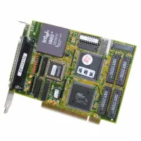
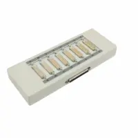
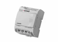
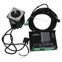
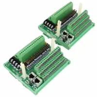

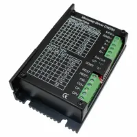
Shop for affordable servo motors and stepper motors designed for maximum torque — even at low speeds — and the highest reliability. We also carry stepper motor drivers, stepper motor controllers, stepper motor power supplies. If you're looking for an all-in-one system we also carry 3D Printers which you can use to prototype and create your very own objecs in 3D. Our stepper motors feature durable construction, making them suitable in a wide range of environments. A new addition to our motion control categories are our Array PLC products. These are excellent value and can be programmed with ease using the free Array programming software available for download.