DIY Low-Frequency Waveform Generator Soldering Project
Welcome to this DIY Low-Frequency Waveform Generator Soldering Project tutorial, where you’ll learn to build a signal generator capable of producing various waveforms. By following this DIY Low-Frequency Waveform Generator Soldering Project, you’ll gain hands-on experience with soldering and assembling electronic components.
What is a Low-Frequency Waveform Generator?
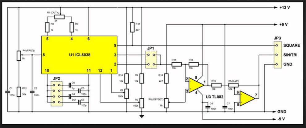
The waveform generator uses a special chip (ICL8038) to produce a signal at a specific frequency, which is adjusted using external controls. The chip generates a square wave signal, which is then shaped into the desired waveform. The signal is then amplified to boost its strength. Finally, the output signal is available at the output terminals, where it can be used for various applications. In this blog post, we’ll guide you through the assembly process and highlight the features and capabilities of the Low-Frequency Waveform Generator.
Application:
- Science Projects: Generate waveforms for science fair projects, such as demonstrating the properties of sound waves.
- Oscilloscope Testing: Test and calibrate oscilloscopes using the signal generator’s precise waveform.
- Audio Equipment Testing: Generate test tones for audio equipment testing, such as speaker testing, amplifier testing, and sound card testing.
- Laboratory Experiments: Use the signal generator to produce waveforms for physics, electronics, and electrical engineering lab experiments.
- Electronic Circuit Design and Testing: Test and debug electronic circuits, such as filters, amplifiers, and oscillators.
Assemble Instruction
Tips before soldering:
- Clean components, PCB, and soldering iron
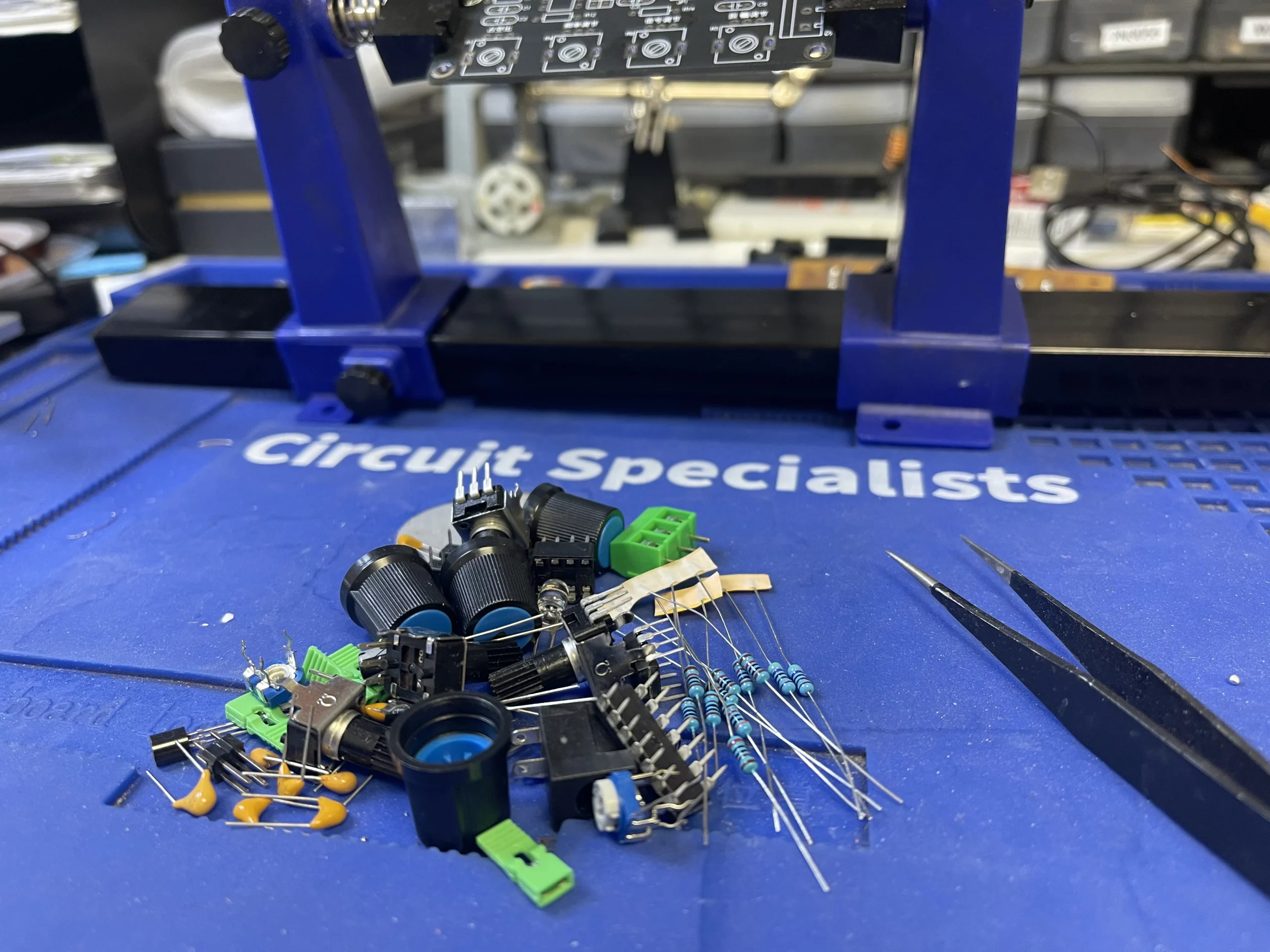
- Prepare components and inspect the PCB
- Set up soldering iron with appropriate tip and temperature
- Practice good soldering technique
- Wear safety glasses and ensure good ventilation
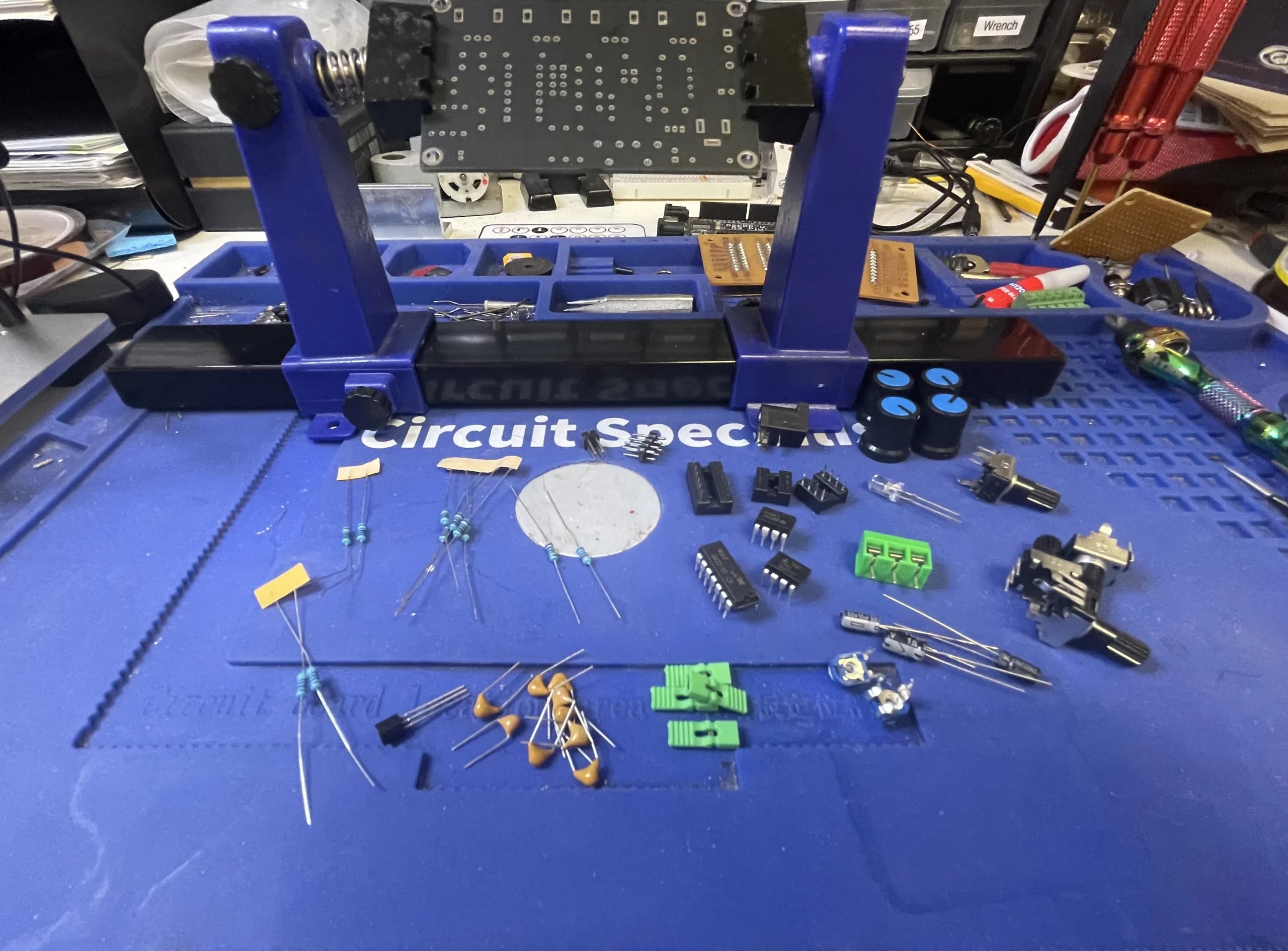
Component Installation
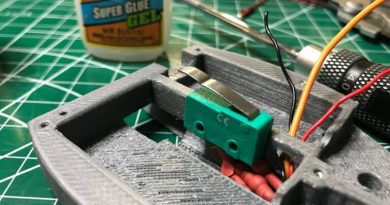
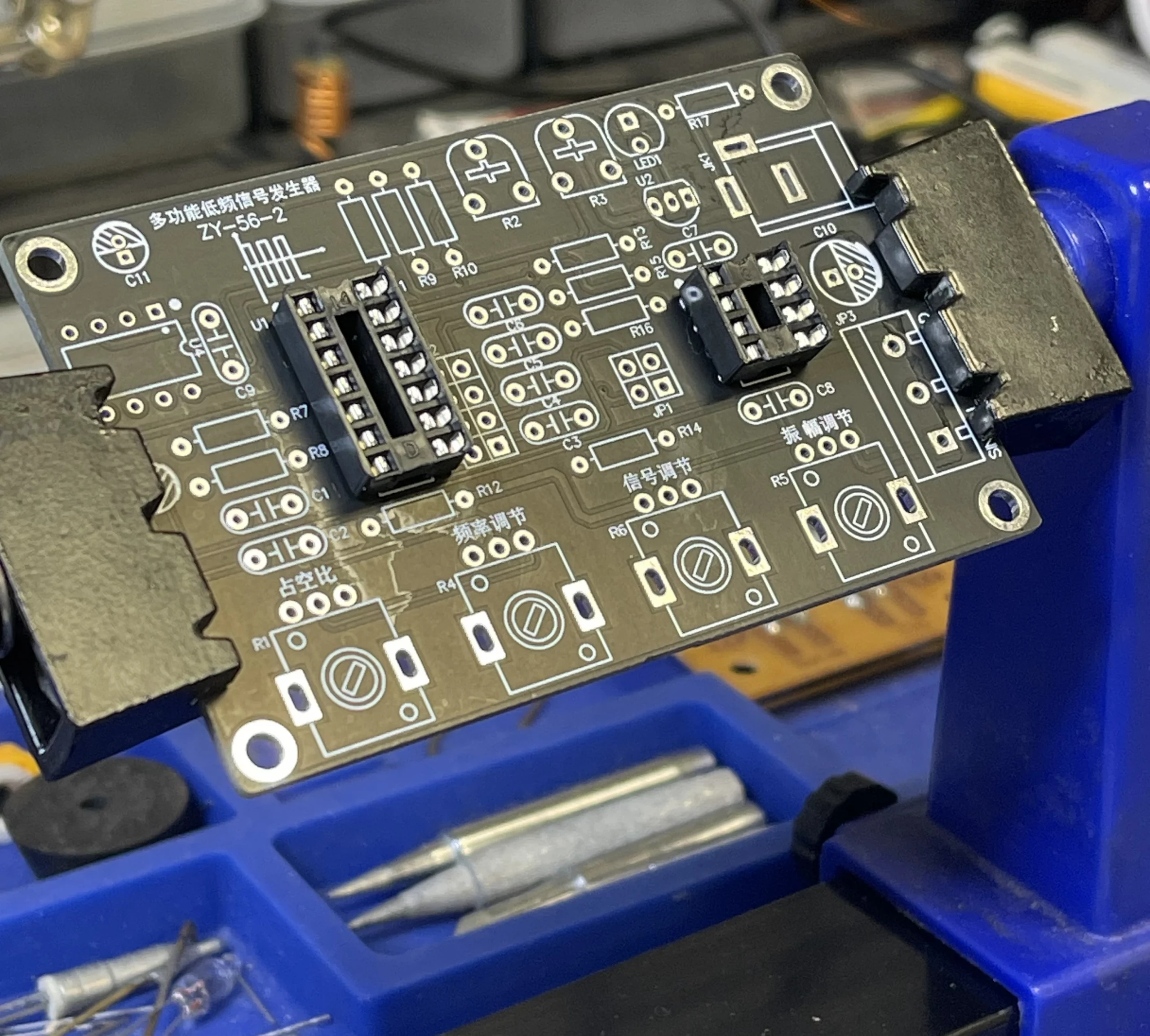
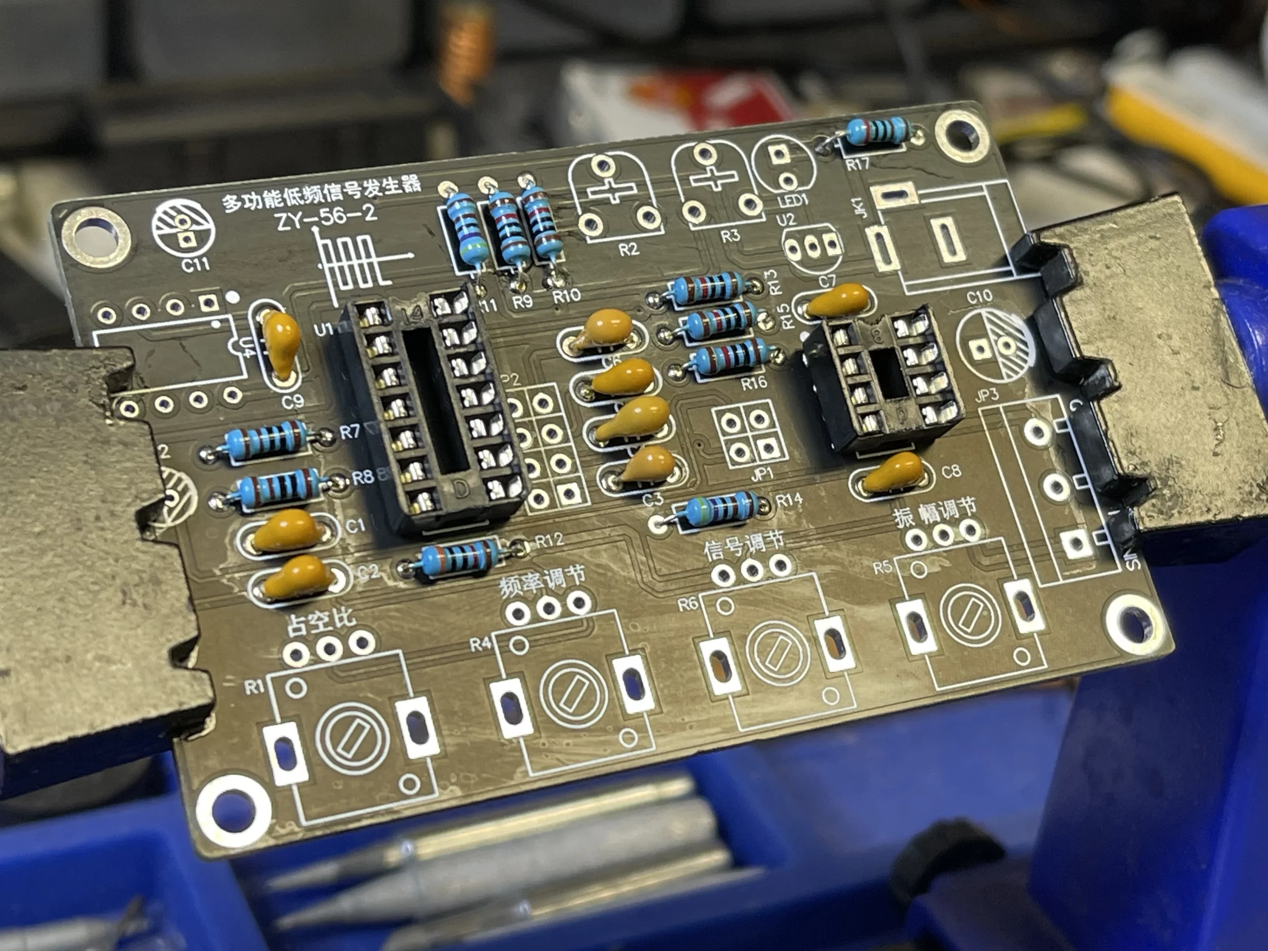
First, solder the IC socket, ensuring it faces the correct direction as indicated on the PCB. I found that the PCB clamp is super helpful throughout.
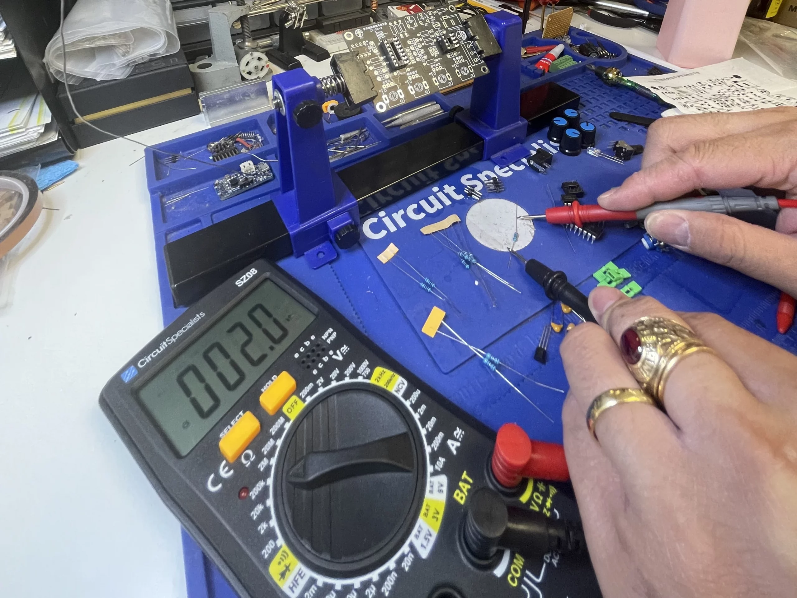
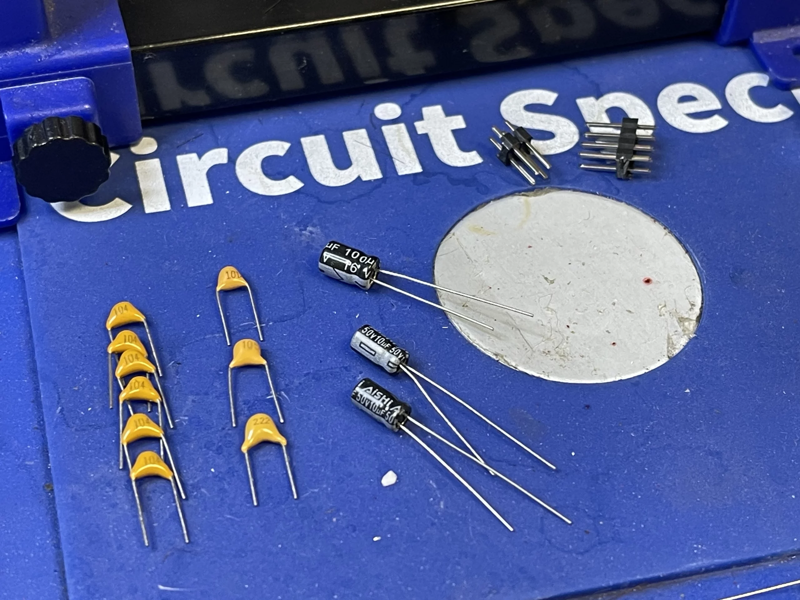
Before soldering all resistors to the assigned location, make sure to use a multimeter to measure the resistor and confirm its resistance value.
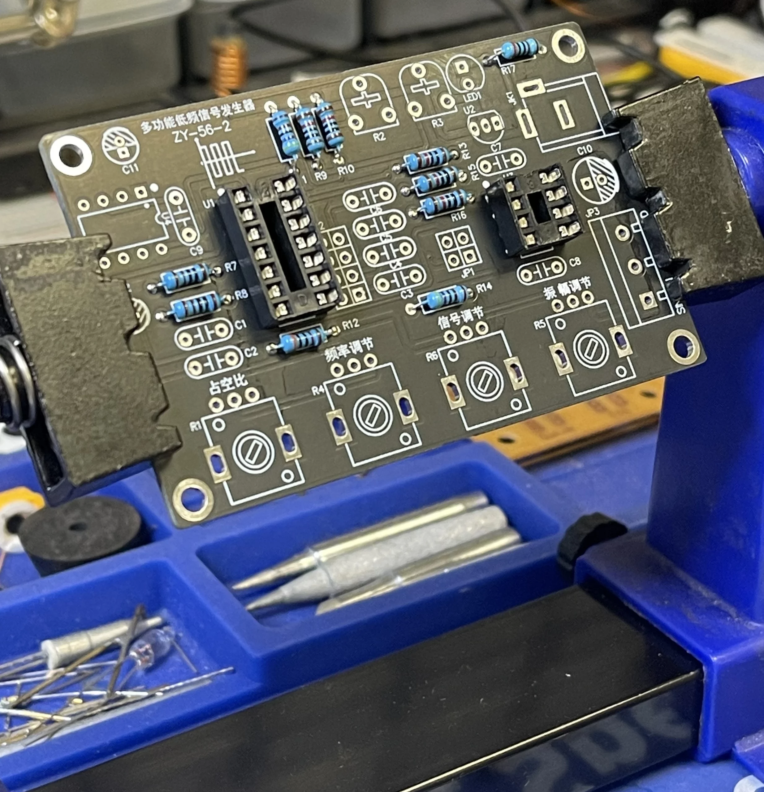
Next, before solder capacitors, verify their capacitance value, and place them in the assigned locations according to the instruction manual.
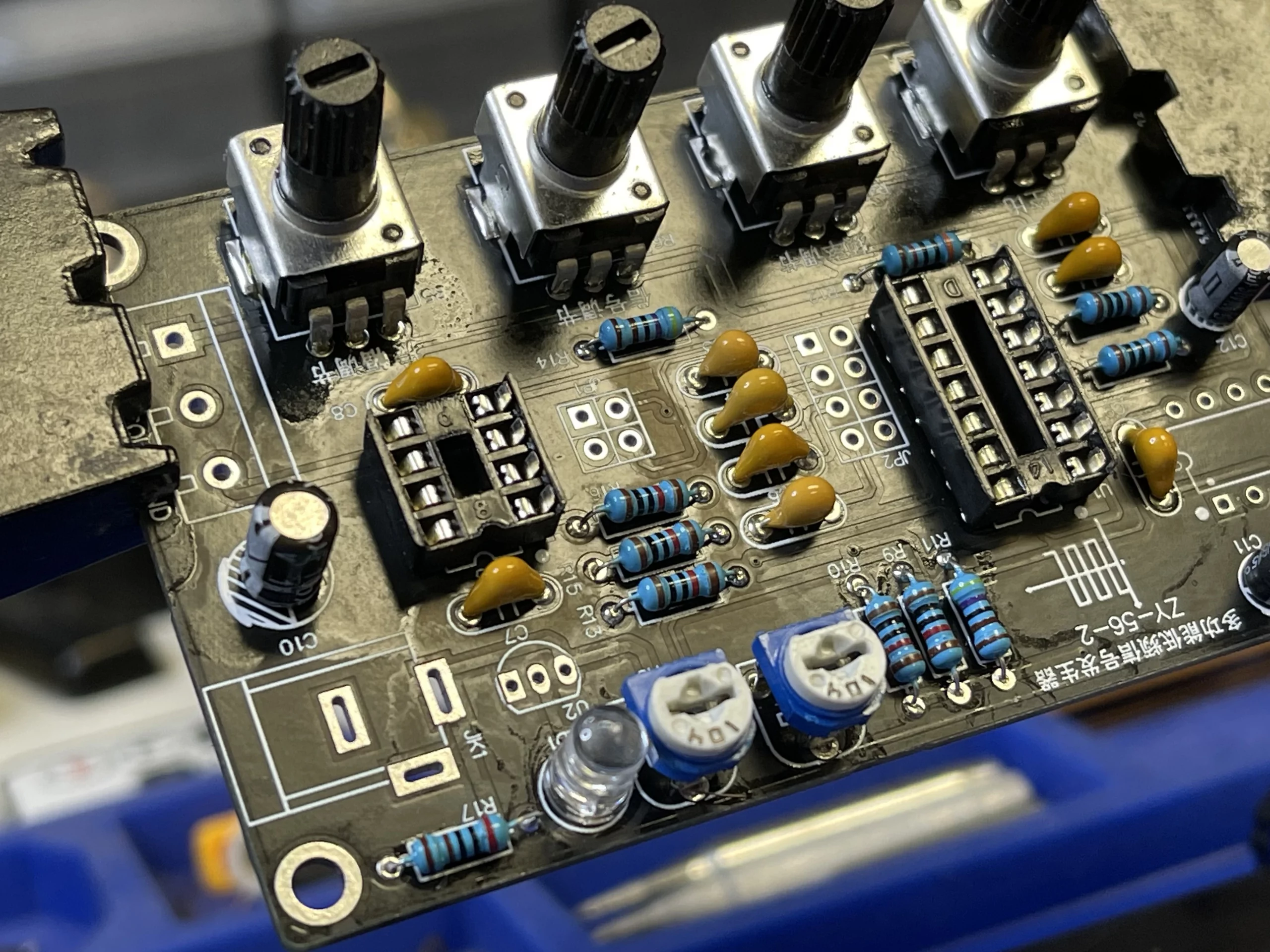
Then solder the potentiometer and trim ports onto the PCB, ensuring the correct potentiometer value in the assigned location.
Finally, solder the power port and signal terminal onto the PCB, completing the PCB assembly process.
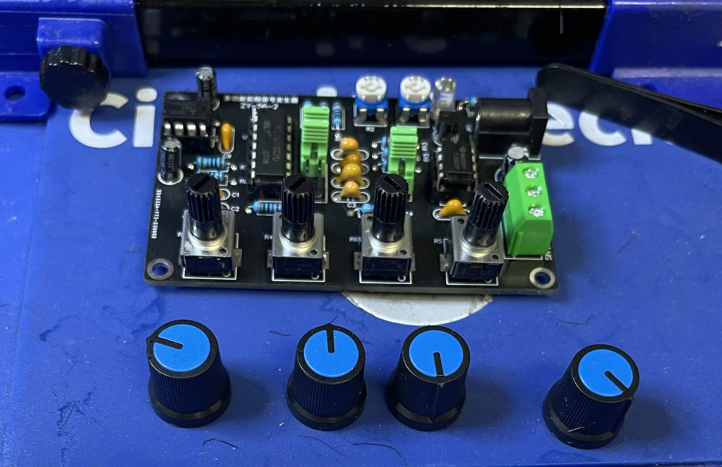
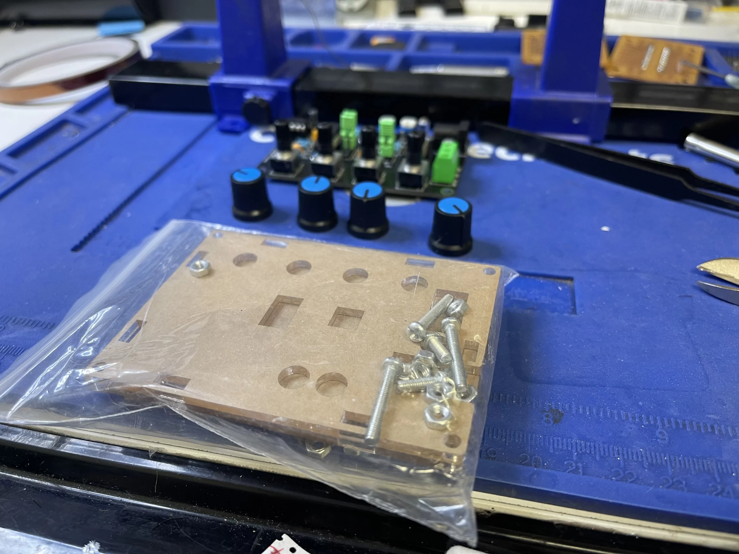
Now, we can assemble the included acrylic enclosure for the waveform generator.
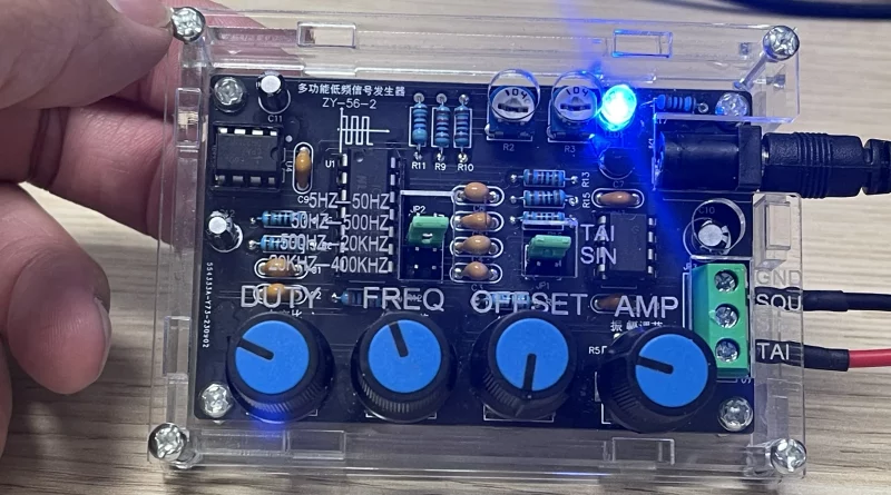
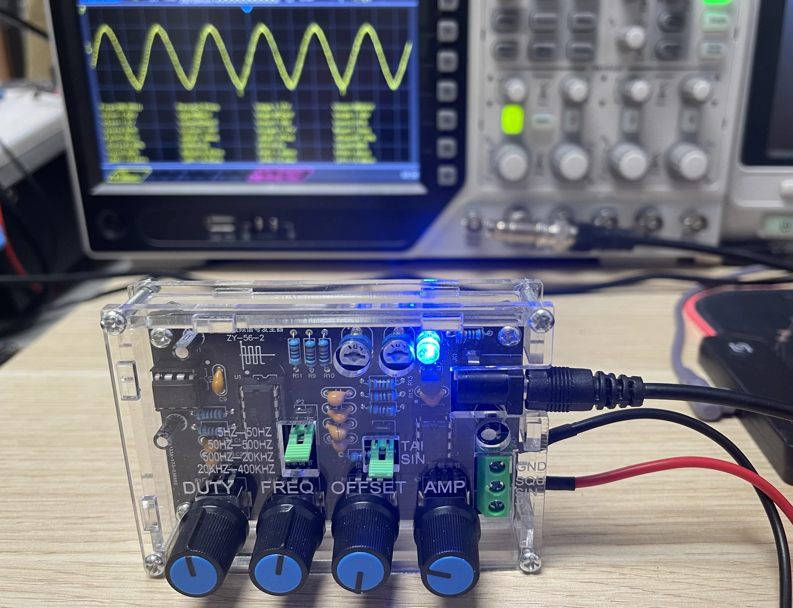
After assembling the acrylic enclosure, now the waveform generator is ready to operate.
In conclusion, building a Low-Frequency Waveform Generator is a rewarding DIY project that not only yields a versatile tool for various applications but also enhances your soldering skills and understanding of circuit theory. By following this guide, you’ve gained hands-on experience with component installation, PCB assembly, and circuit construction. Take your newfound skills to the next level by experimenting with different waveforms, exploring circuit modifications, and applying your knowledge to future electronics projects. Remember, practice soldering and learning circuit theory are key to unlocking the world of electronics – keep building, and keep learning!