Let’s Build Our Most Popular DIY FM Radio Soldering Kit
Welcome to our DIY FM Radio Soldering Kit tutorial! Are you an electronic hobbyist, enthusiast, or college student looking to dive into the world of FM radio circuits and hone your soldering skills? You’re in the right place! By following this DIY FM Radio Soldering Kit tutorial, you’ll gain hands-on experience with electronics and soldering.
In this tutorial, we’ll guide you through the assembly process, sharing valuable tips and tricks to ensure a successful build. Whether you’re a beginner or an experienced maker, this project is an excellent way to enhance your knowledge and skills in electronics.
Part list
Before we begin, make sure you have all the necessary components and tools. Here’s a list of what’s included in the Circuit Specialists DIY FM Radio Kit:
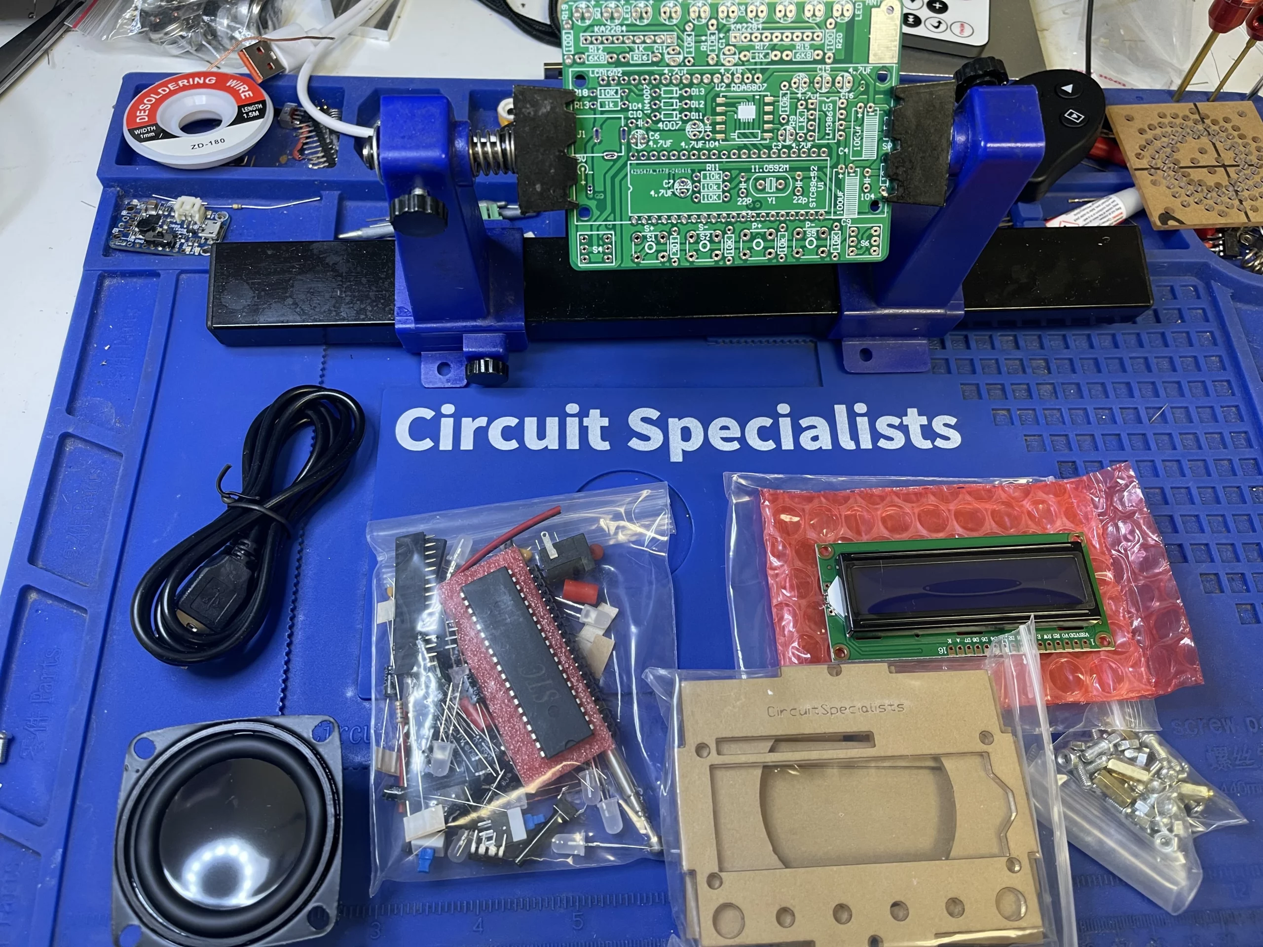
- RDA5807 FM Radio Receiver module
- LCD1602 display screen
- RGB spectrum indicator
- Volume control potentiometer
- Power amplifier component
- Capacitors, resistors, and other passive components
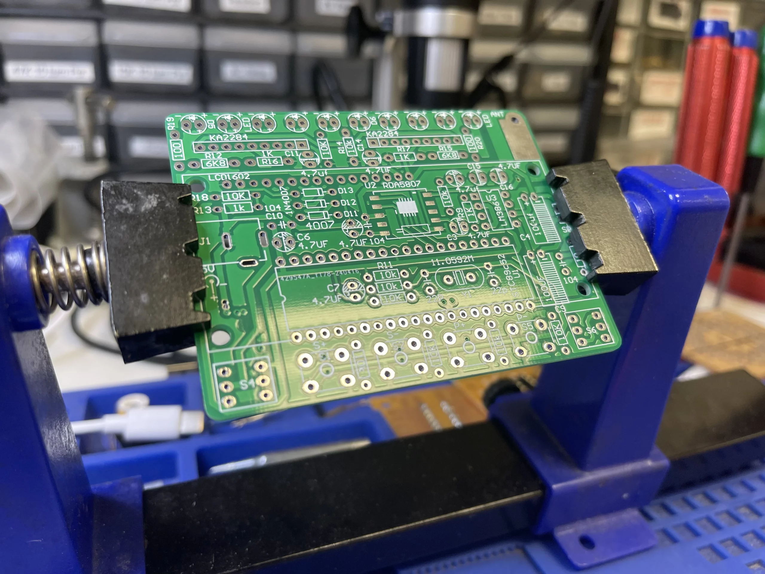
- PCB board
- Jumper wires
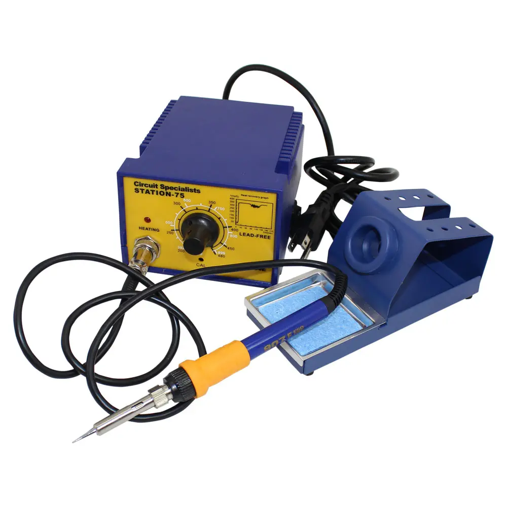
The key to success with this soldering kit, or any soldering kit, is a good soldering station. A reliable station provides stable power for consistent temperature control, making all the difference in your soldering experience. If you’re just starting out, consider investing in a quality beginner soldering station like the CSI-STATION 75. Its temperature control and stability will help you achieve professional-grade solder joints and ensure a successful build.
Additional Tools:
- Soldering iron tip cleaner
- Solder wick
- Multimeter (optional)
- Anti-static wrist strap (optional)
The Schematic
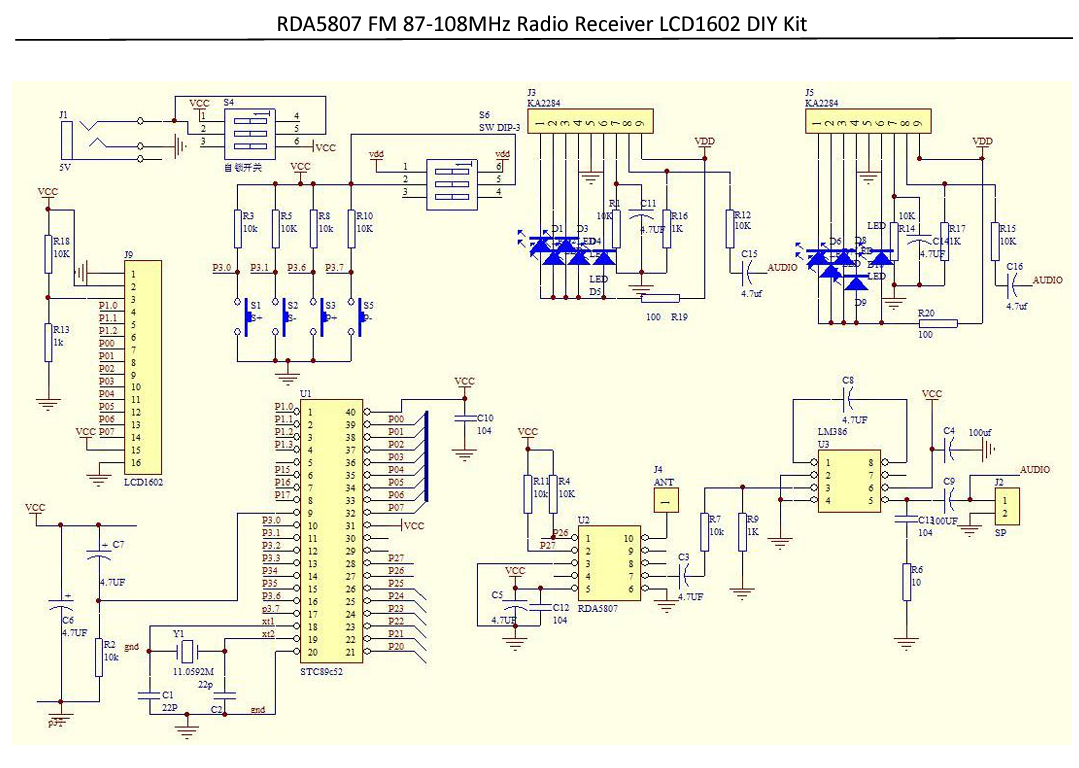
The RDA5807 is an FM radio receiver integrated circuit (IC) that processes incoming FM signals to produce audio output. It receives the FM signal through an antenna, tunes into the desired frequency (87-108 MHz) using its internal tuner, and demodulates the signal to extract the original audio information. The demodulated audio is then processed and amplified, and the final audio output is sent to a speaker. Please note that this is a high-level overview, and the actual internal workings may involve more complex digital signal processing and filtering.
Soldering Process
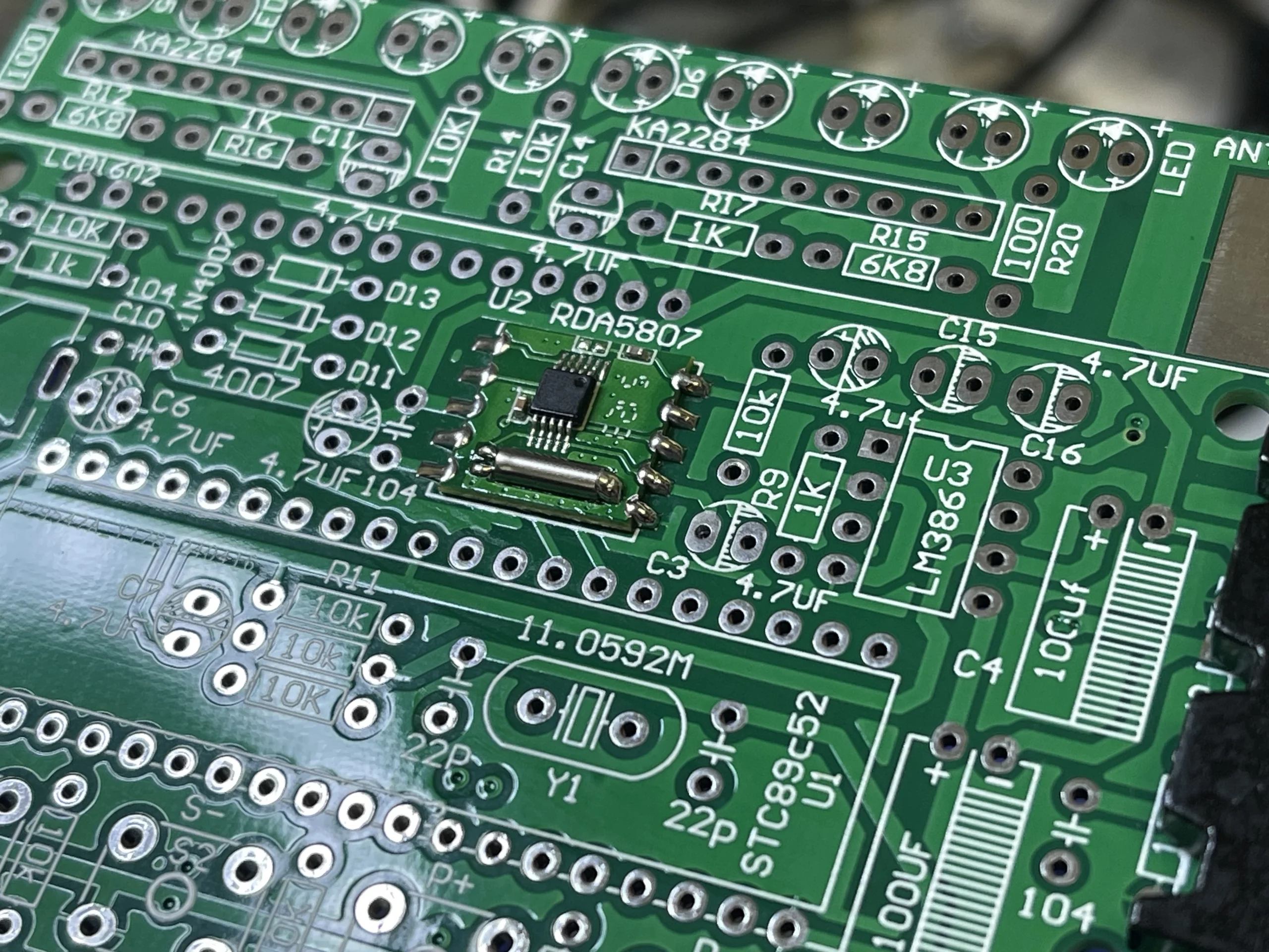
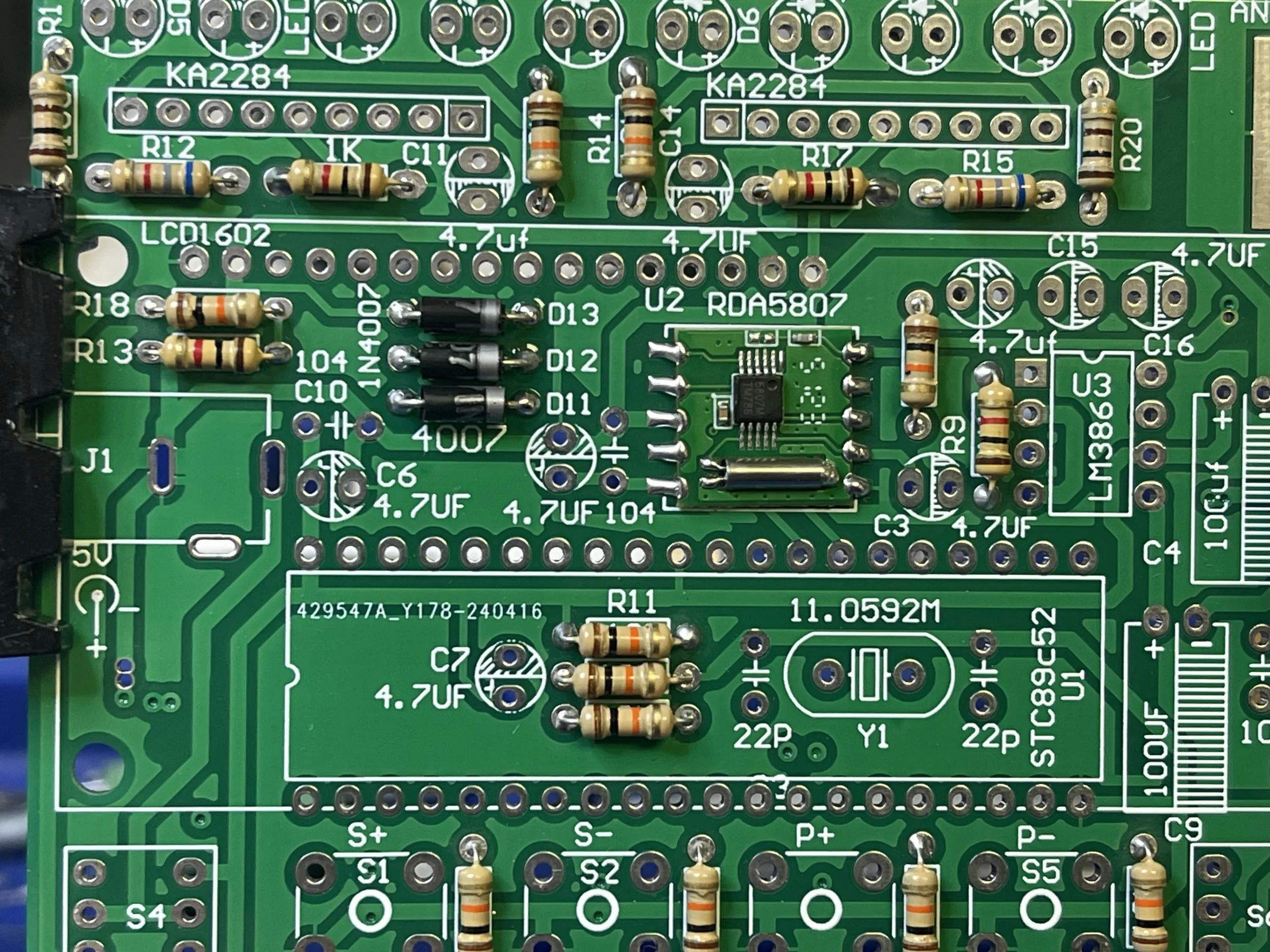
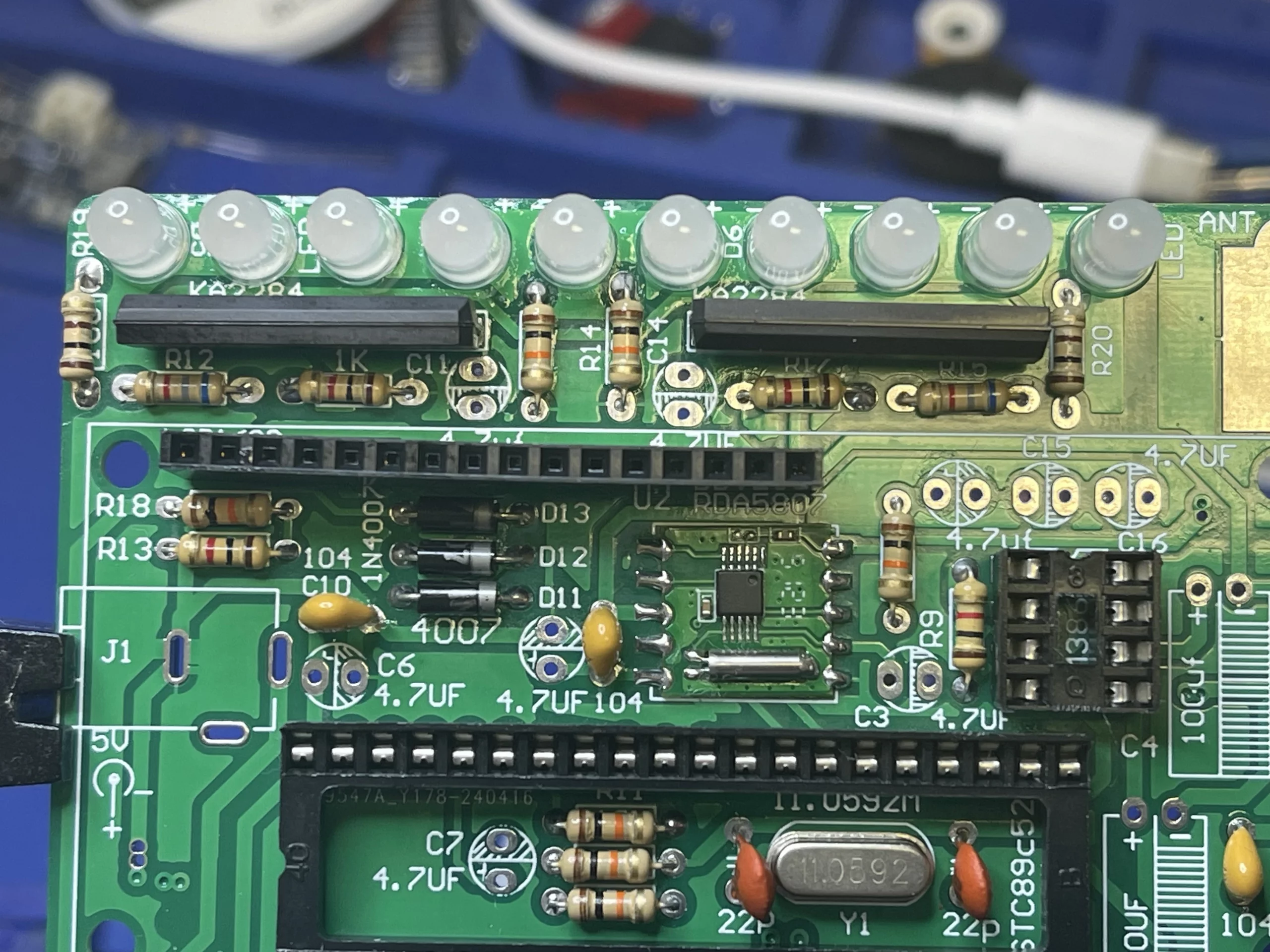
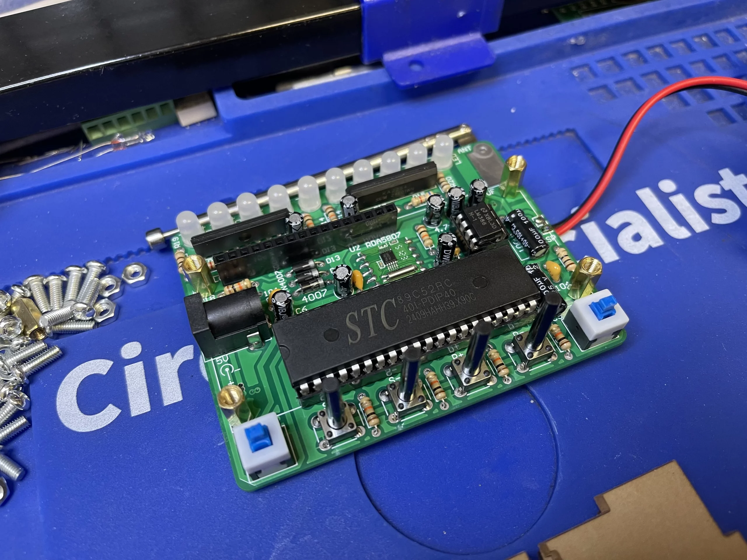
Step 1: Solder RDA5807 FM Radio Receiver
One of the first things that need to solder onto the PCB is the RDA5807 FM radio receiver. In this kit, the RDA5807 is the brain of the FM radio, responsible for tuning into stations, decoding signals, and producing clear audio output. Its compact size and ease of use make it an ideal choice for this DIY FM Radio Project.
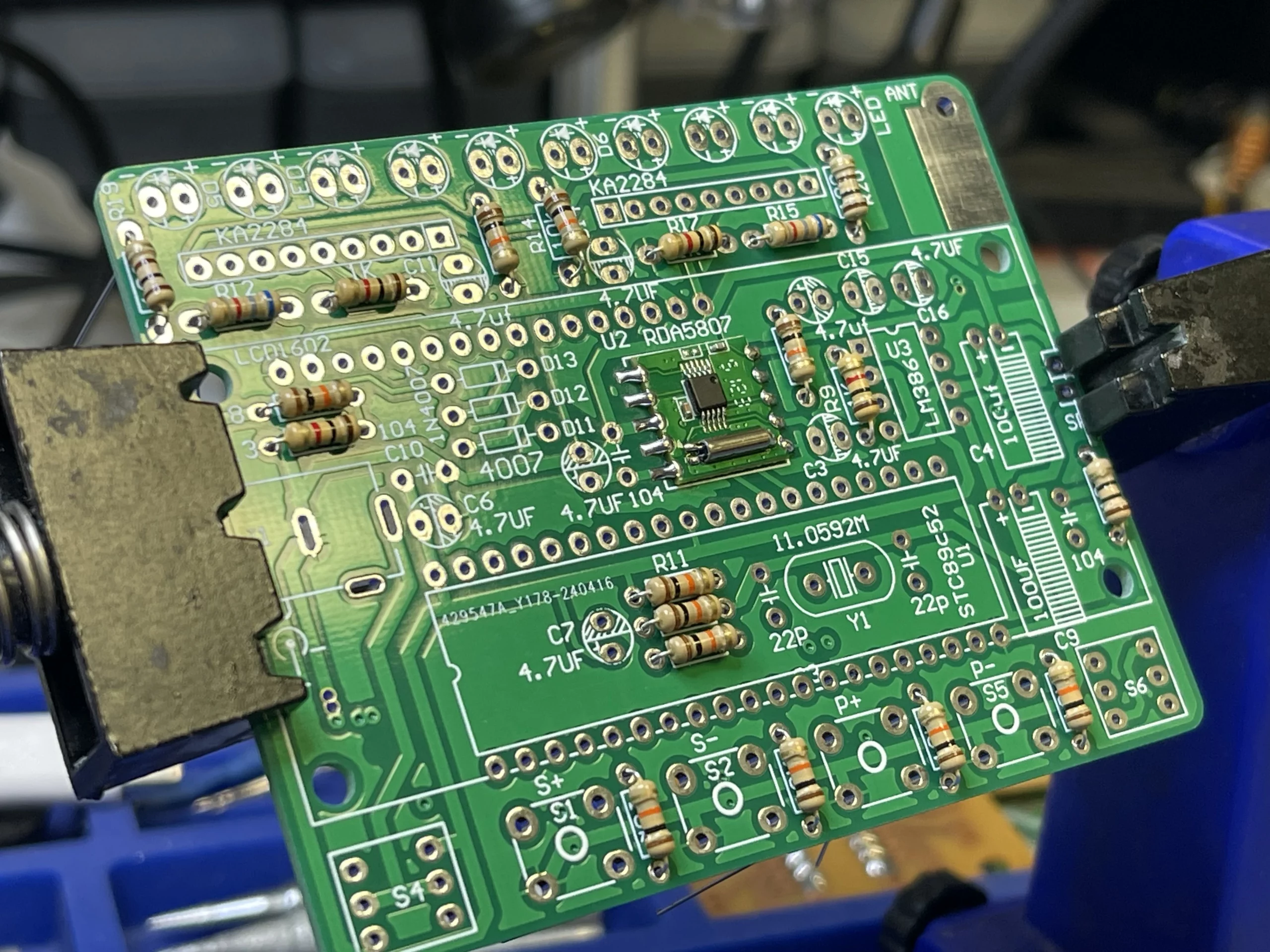
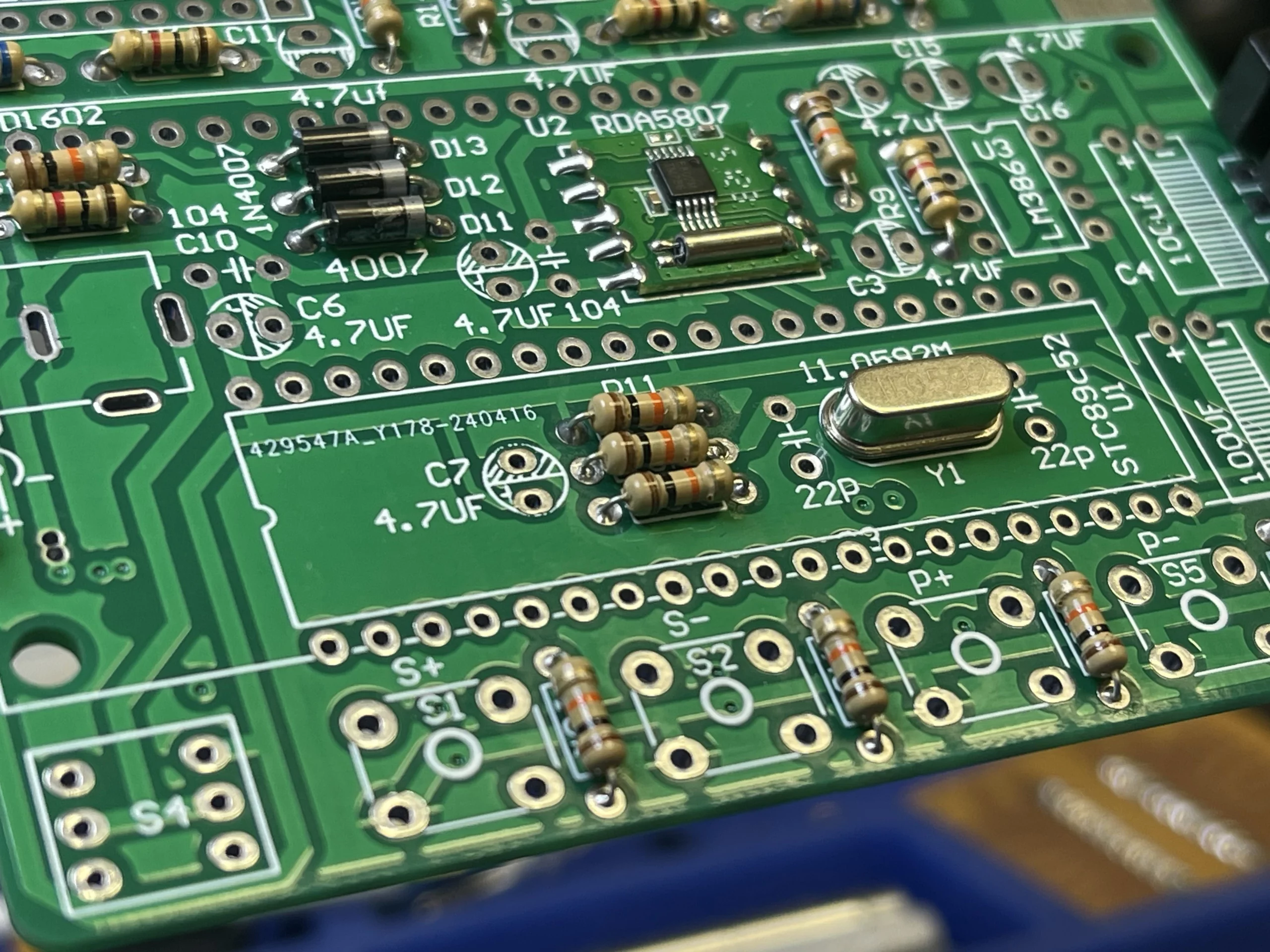
Step 2: Solder Resistors
Solder resistors onto the PCB according to the markings. Measure each resistor with a multimeter before soldering to avoid mix-ups.
Step 3: Solder Diode
When soldering the diode, it is important to make sure the polarity of the diode according to the marks on the PCB.
Step 4: Solder 11.0592 MHz Crystal Oscillator
This crucial component provides a stable frequency reference for accurate tuning and clear audio output.
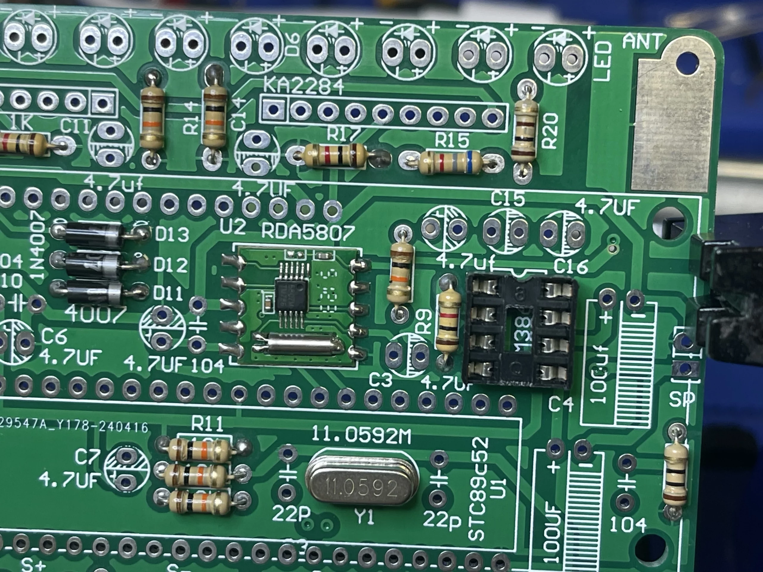
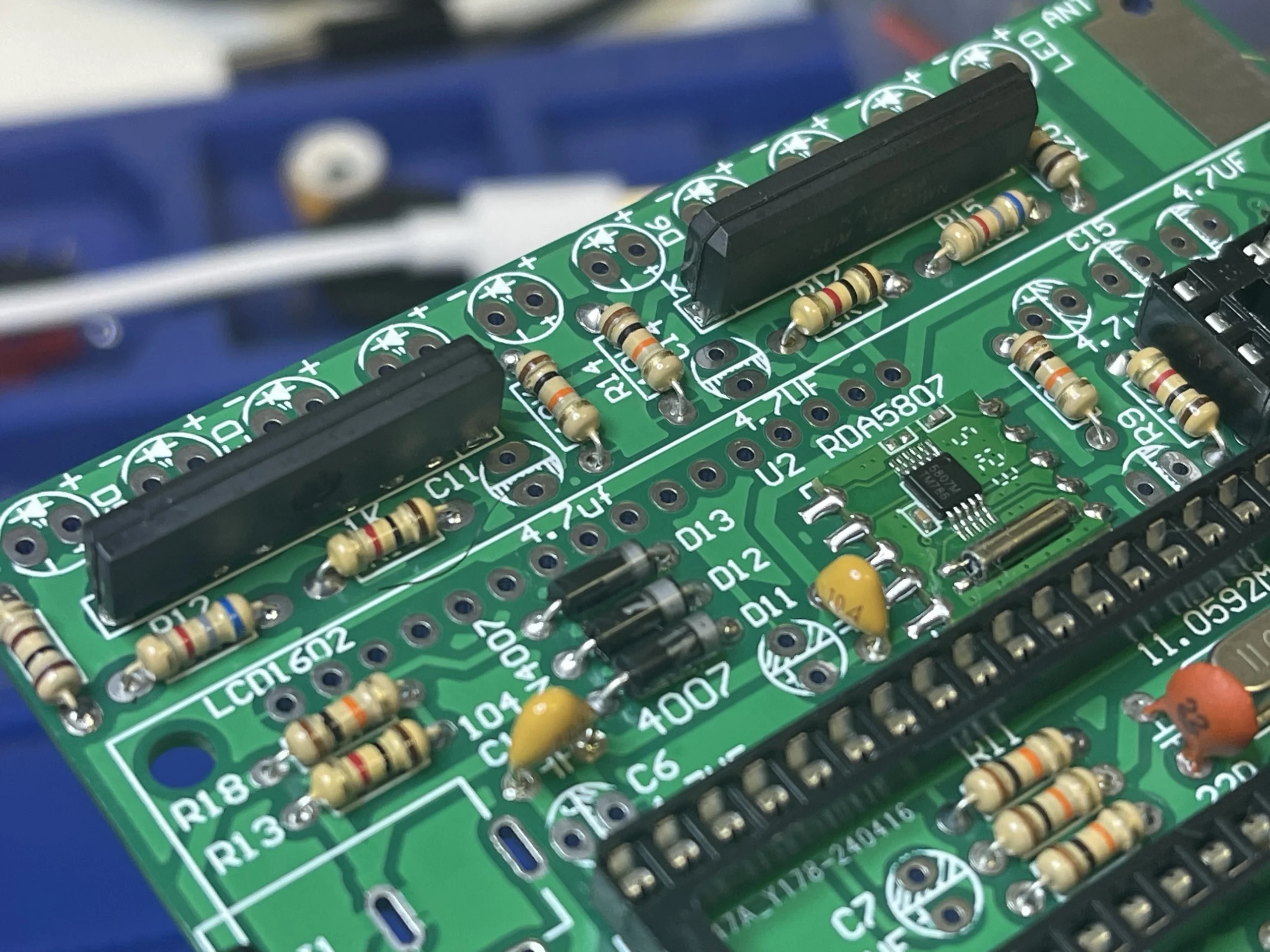
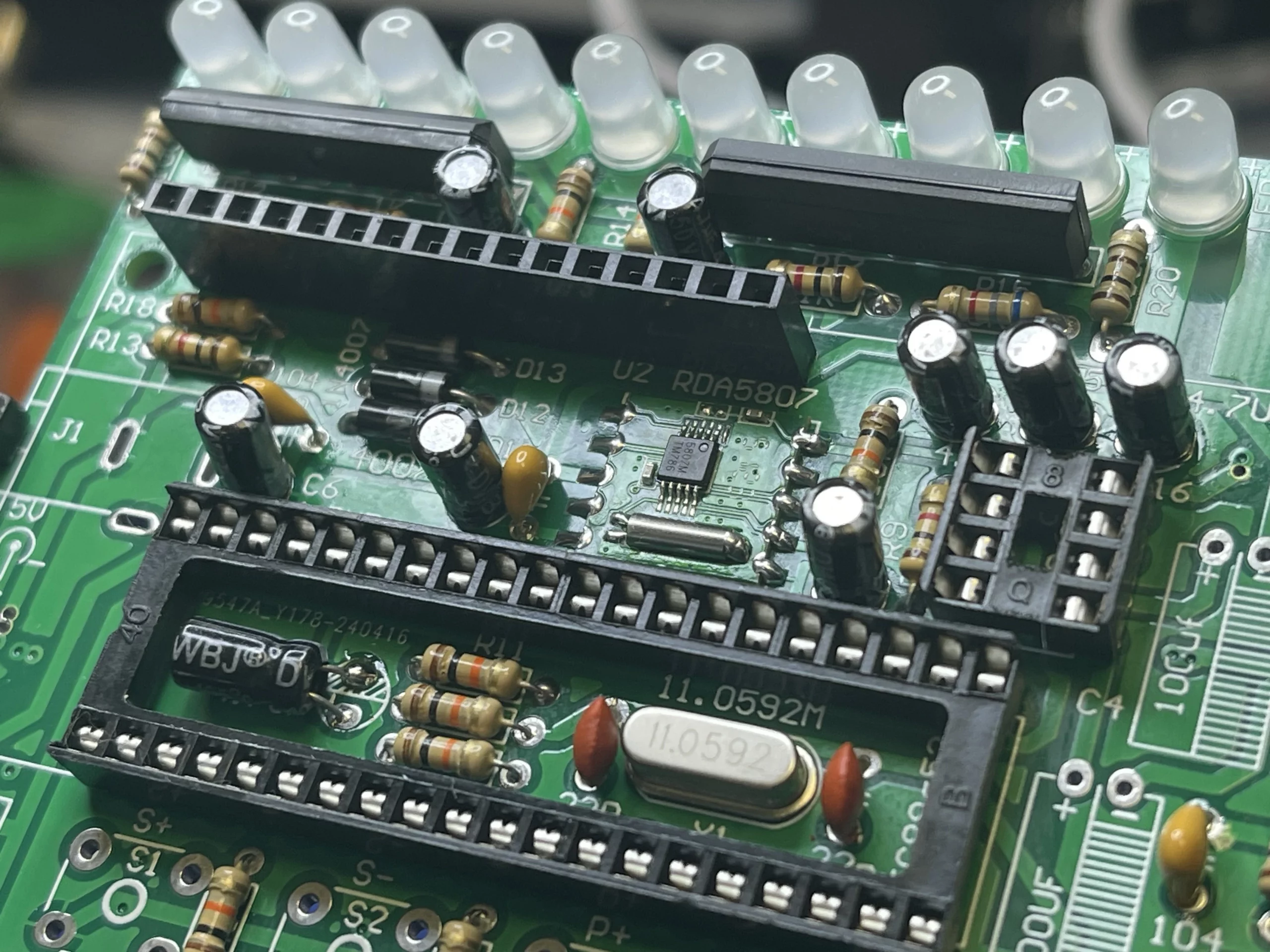
Step 5: Solder IC Sockets
The IC socket came with a mark on the top to make sure the IC socket was orientated correctly.
Step 6: Solder the KA2284
When soldering the KA2284 onto the PCB, make sure they orientate correctly, the marking on the PCB is really helpful in this case. The KA2284 is a power amplifier IC used in the FM radio circuit to amplify the audio signal from the RDA5807 FM radio receiver.
Step 7: Solder Header Pin Socket
Now, solder the header pin socket onto the PCB, the thing to look out for in this step would be making sure the header pin socket seat is flush and square with the PCB.
Step 8: Solder Capacitors
The most important part of soldering capacitors is making sure the capacitor polarity matches the polarity on the PCB. The capacitor negative is usually marked on the capacitor’s body.
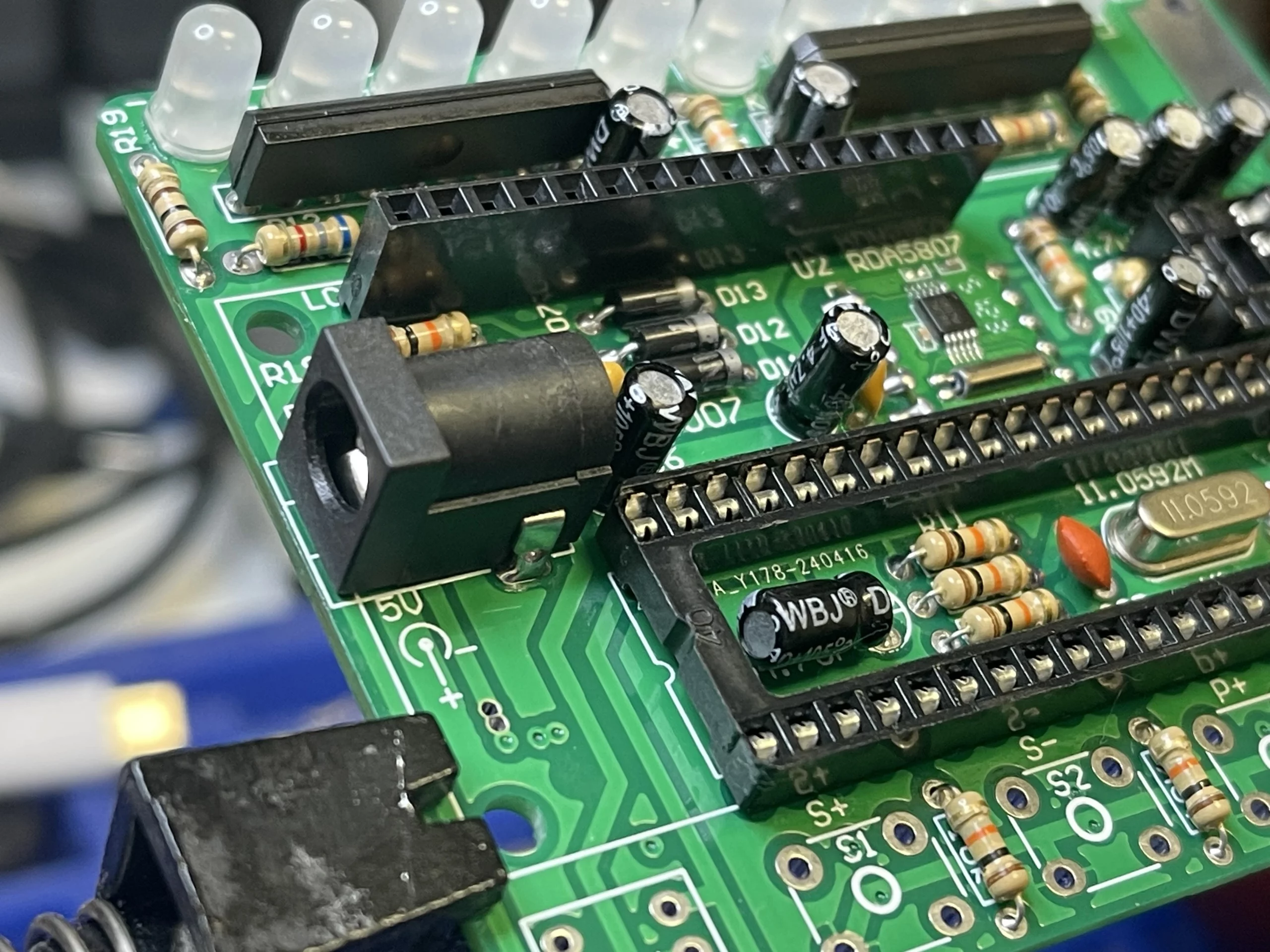
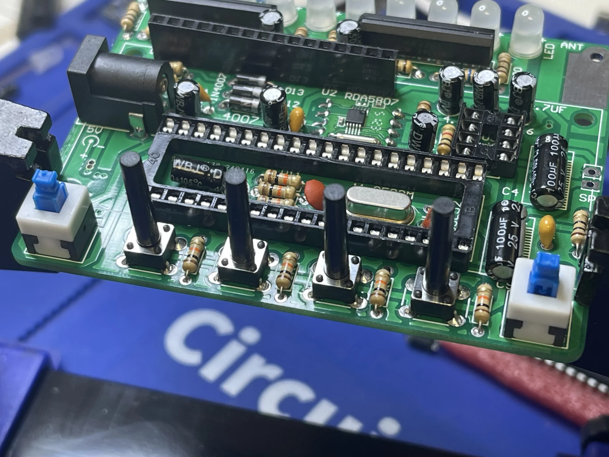
Step 9: Solder Power Port and Switches
Solder the power port onto the PCB, and make sure the port is flush and square with the marking on the PCB. This will ensure the enclosure will fit nicely later.
Similar to the power port, it is important to make sure the switches are seated flush and square to the marking on the PCB to ensure the enclosure fits nicely later.
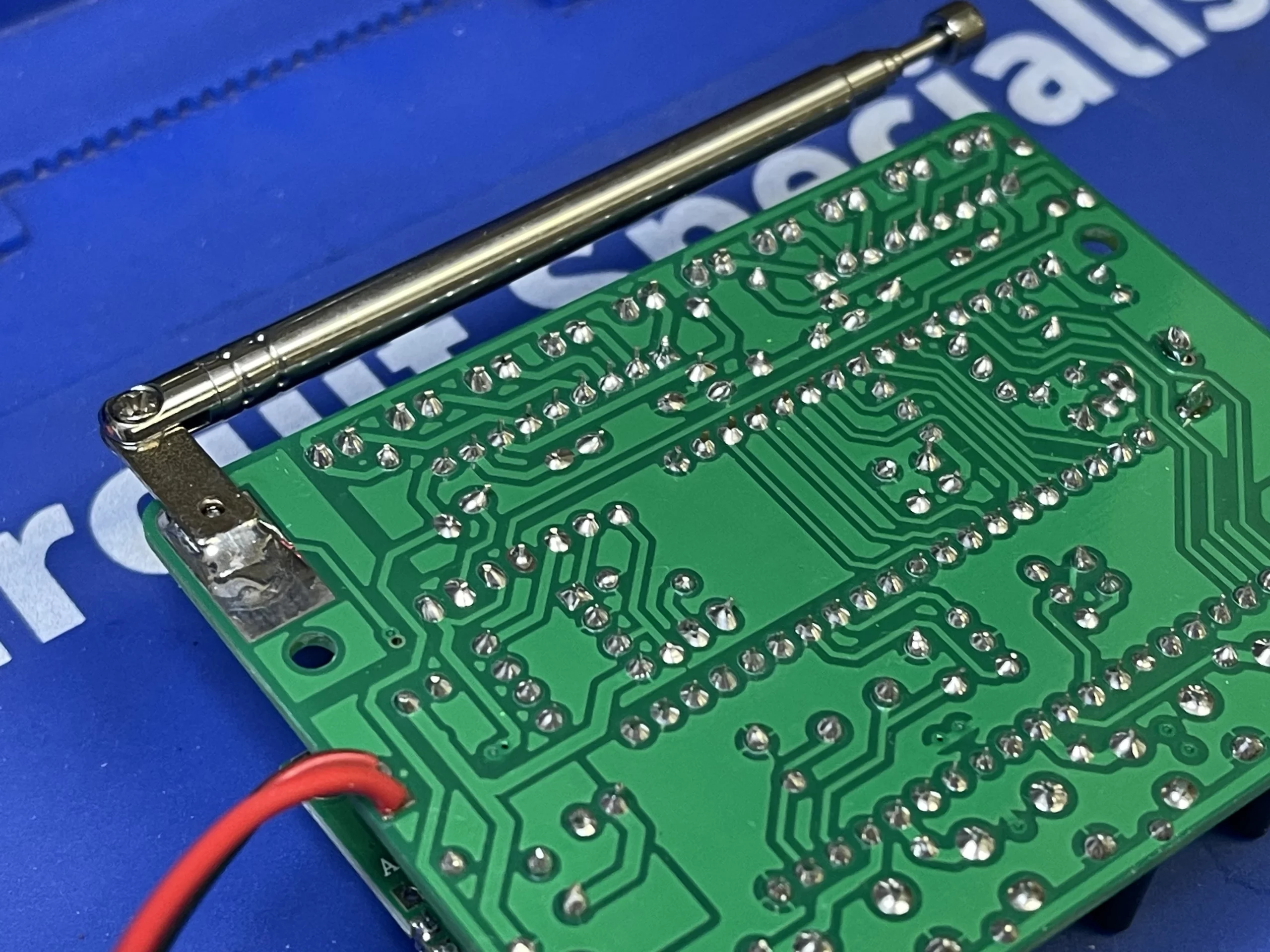
Step 10: Solder Antenna
When soldering the antenna onto the PCB, make sure to use extra flux and tin the tip of the antenna and the path first before the soldering process.
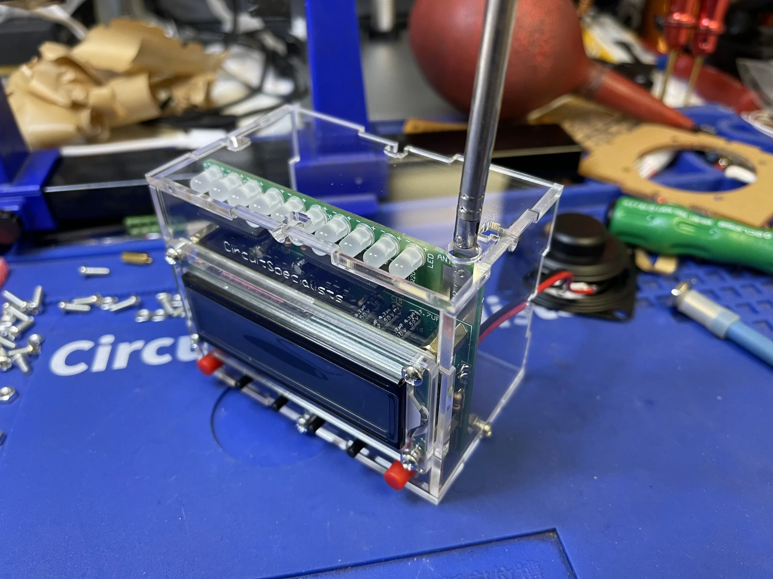
Step 11: Install LCD and Speaker
Make sure to install the 4 brass standoff before installing the LCD onto the PCB.
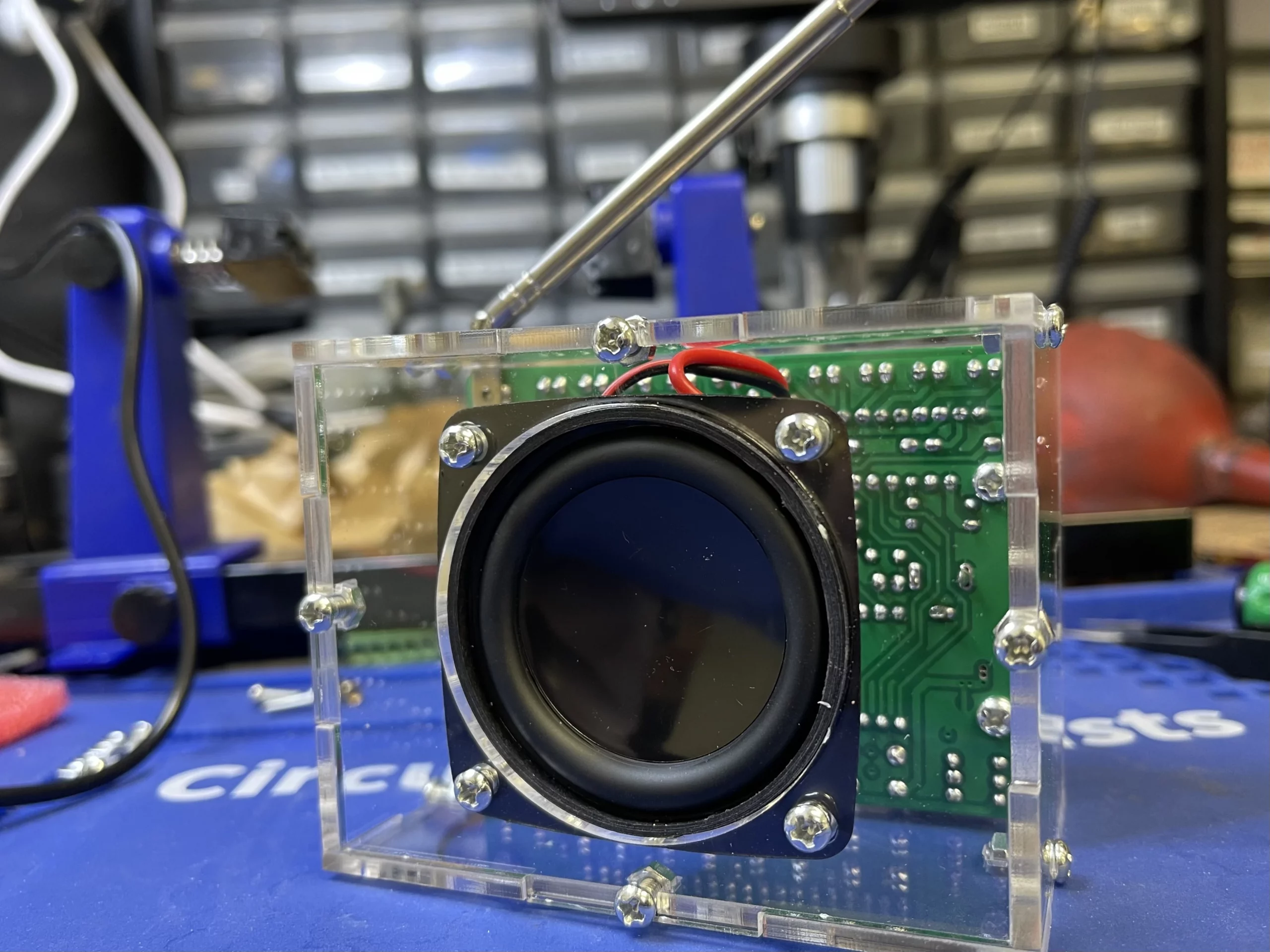
Step 12: Enclosure Assemble process
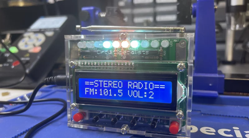
Before assembling the enclosure, make sure to test the FM radio functionality. In addition, please check the instruction manual for details on how to assemble the enclosure.
Make sure to install the speaker onto the back panel before attempting to put the pack panel on the enclosure
Troubleshooting Tips
- Check for correct polarity and orientation
- Ensure secure connections
- Consult the instruction manual for troubleshooting guides
Conclusion
Congratulations on completing the Circuit Specialists DIY FM Radio Kit tutorial! You now have a fully functional FM radio and enhanced soldering skills. A reliable soldering station, such as the CSI-STATION 75, played a crucial role in your successful build. Remember, a good soldering station provides stable power, consistent temperature control, and professional-grade solder joints. Invest in a quality soldering station to enhance your soldering experience and ensure successful builds. Share your experience and happy building!