From Prototype To Finished Product with PBB-272C Powered Breadboar
Prototyping is an essential step in the electronics design process, allowing makers and DIY enthusiasts to test and refine their ideas before moving to a final product. In this tutorial, we’ll show you how to take a prototype to a finished product using a Power Breadboard PBB-272 Series. We’ll explore the benefits of using a Power Breadboard PBB-272C and demonstrate how to integrate the circuits into a complete sound and light system.
Table of Content
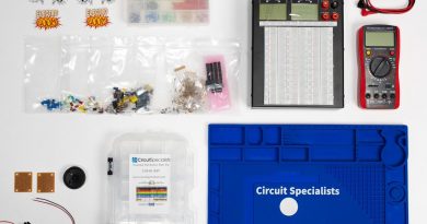
- Part List
- Circuit diagram
- How the Circuit Works
- What is an Emergency Box?
- Build the Circuits onto a Solderable Board
- How to Cut the Pattern for Speaker and Light
- How to wire the Emergency! Box
- Conclusion
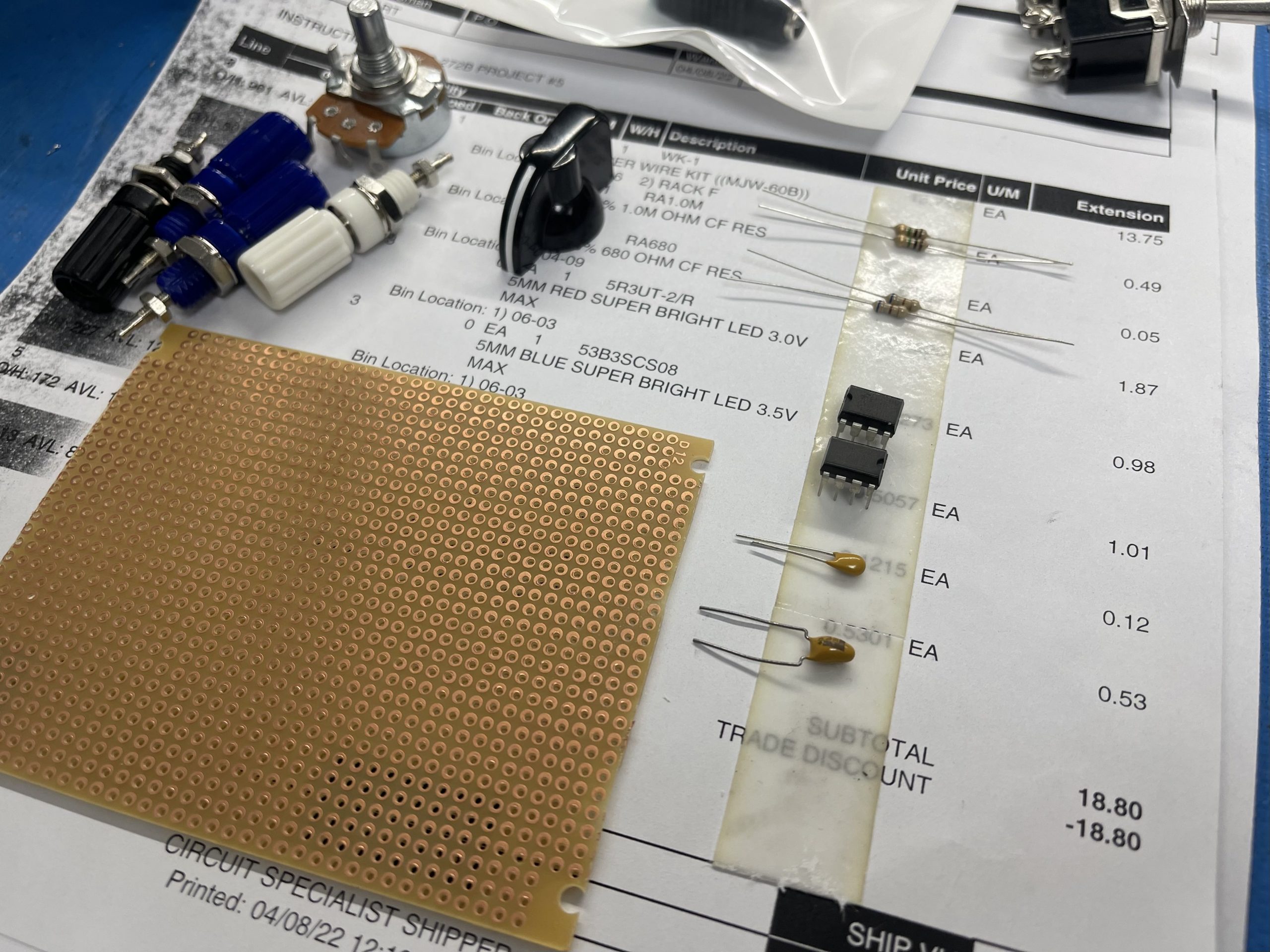
Part List
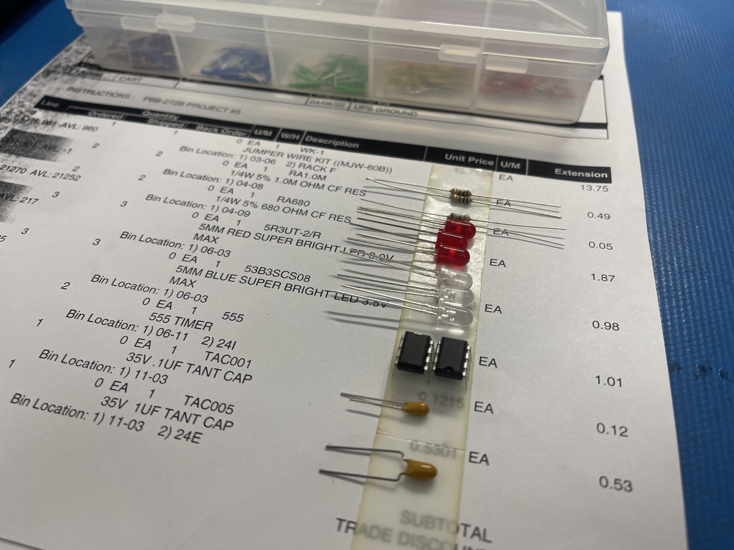
- 2 x 555 Timer
- LEDs: 3 x Red, 3 x Blue
- Resistors: 2 x 1M, 2 x 68Ohm
- Capacitors: 1uF, 100nF
- Power Breadboard PBB-272B
- Jumper Wire
- Aluminum Enclosure
- 4 Binding Posts
- On/Off/On Switch
- 2 Solderable Boards
Note: Depending on the power supply used and the way LEDs are connected, either series or parallel. You need to use a different resistor than 68R used in series with the LED. You can read this article 5 Steps to Calculate the Resistor value for LEDs to learn more.
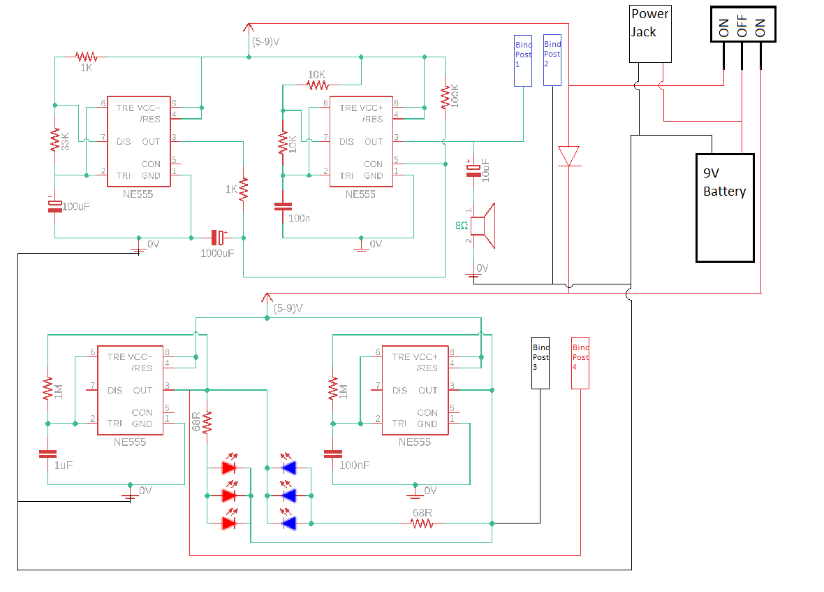
Circuit Diagram
How This Circuit Works
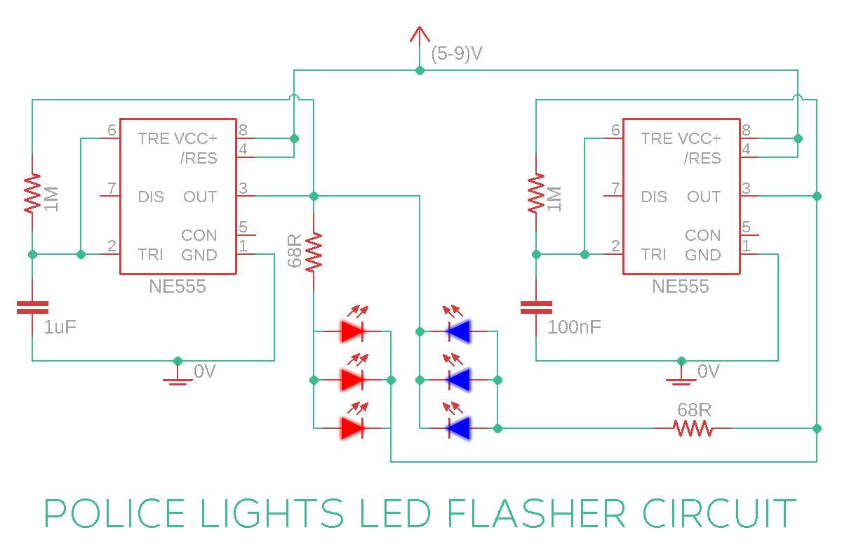
We’ll configure two 555 timers in astable mode, each with different frequencies. The first timer uses a larger capacitor, toggling the output slower, while the second timer uses a smaller capacitor, toggling faster. The LEDs are arranged in opposite polarity, so they toggle ON and OFF at regular intervals.
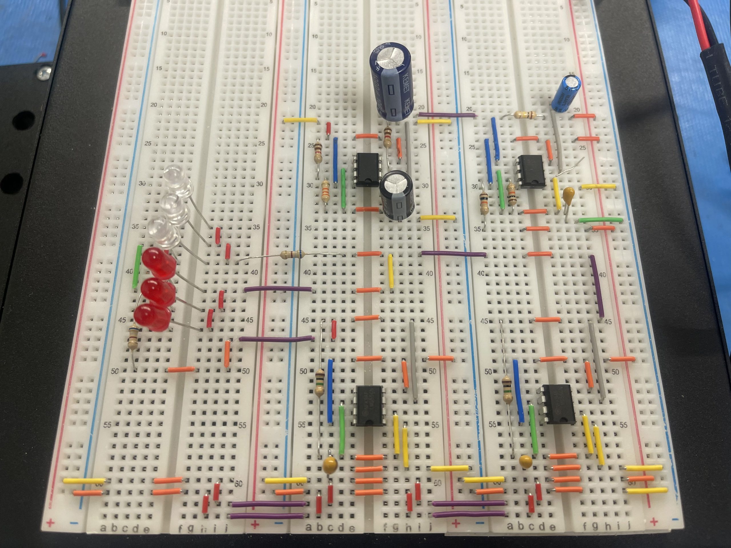
In this police strobe lights style flashing LED circuit, we have used two copies of similar astable circuits configured at different frequencies. The first 555 timer IC, uses a bigger capacitor and so it takes more time to toggle the output. The second 555 timer IC uses a smaller capacitor so it toggles the output very fast.
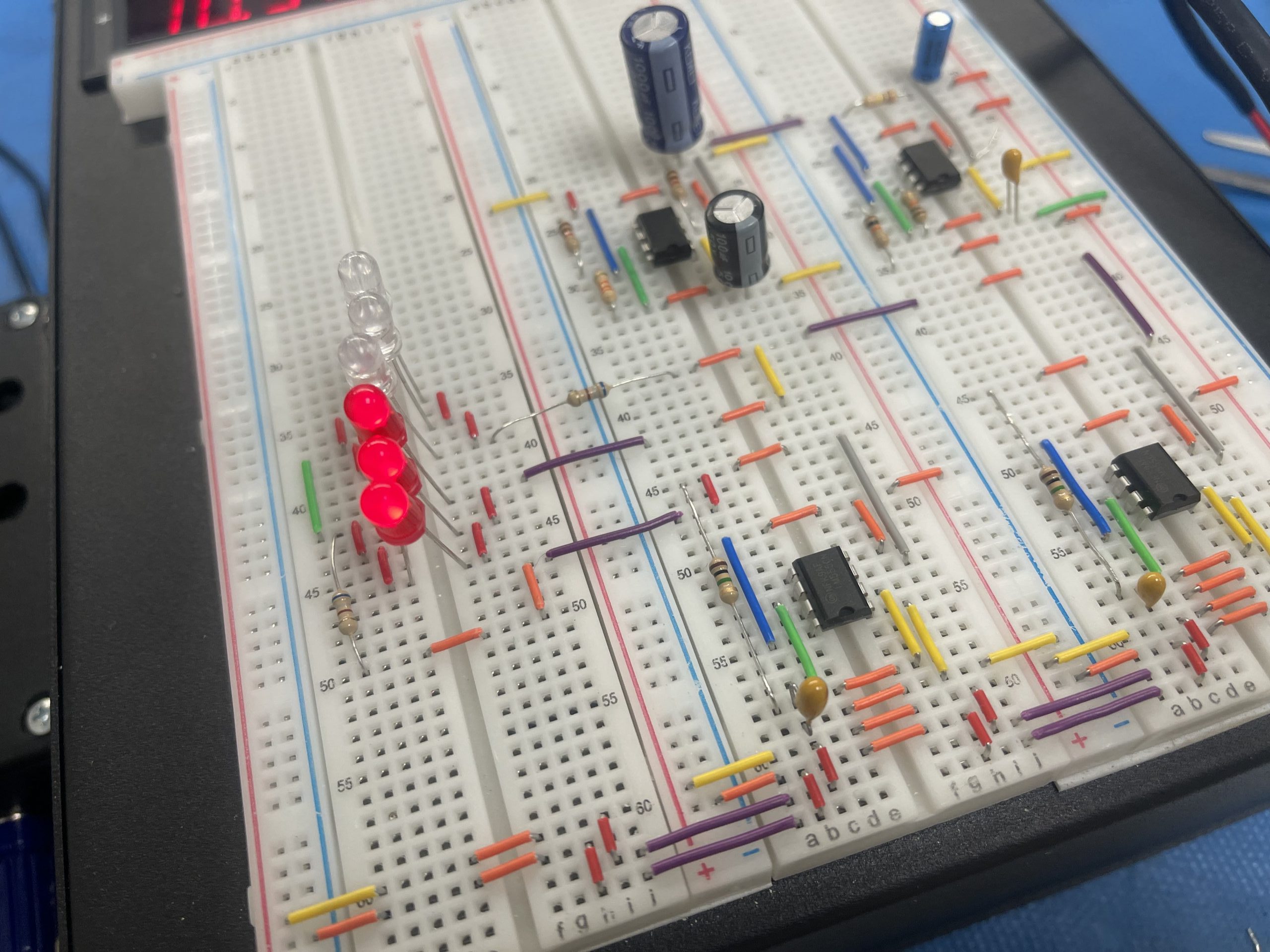
Now coming to the arrangement of LEDs, The first LED group (Red LEDs) turns ON when there is a positive voltage at the anode and a negative voltage at the cathode. This scenario happens when the output of the first 555 timer IC is ON and the output of the second 555 timer IC is OFF at the same time.
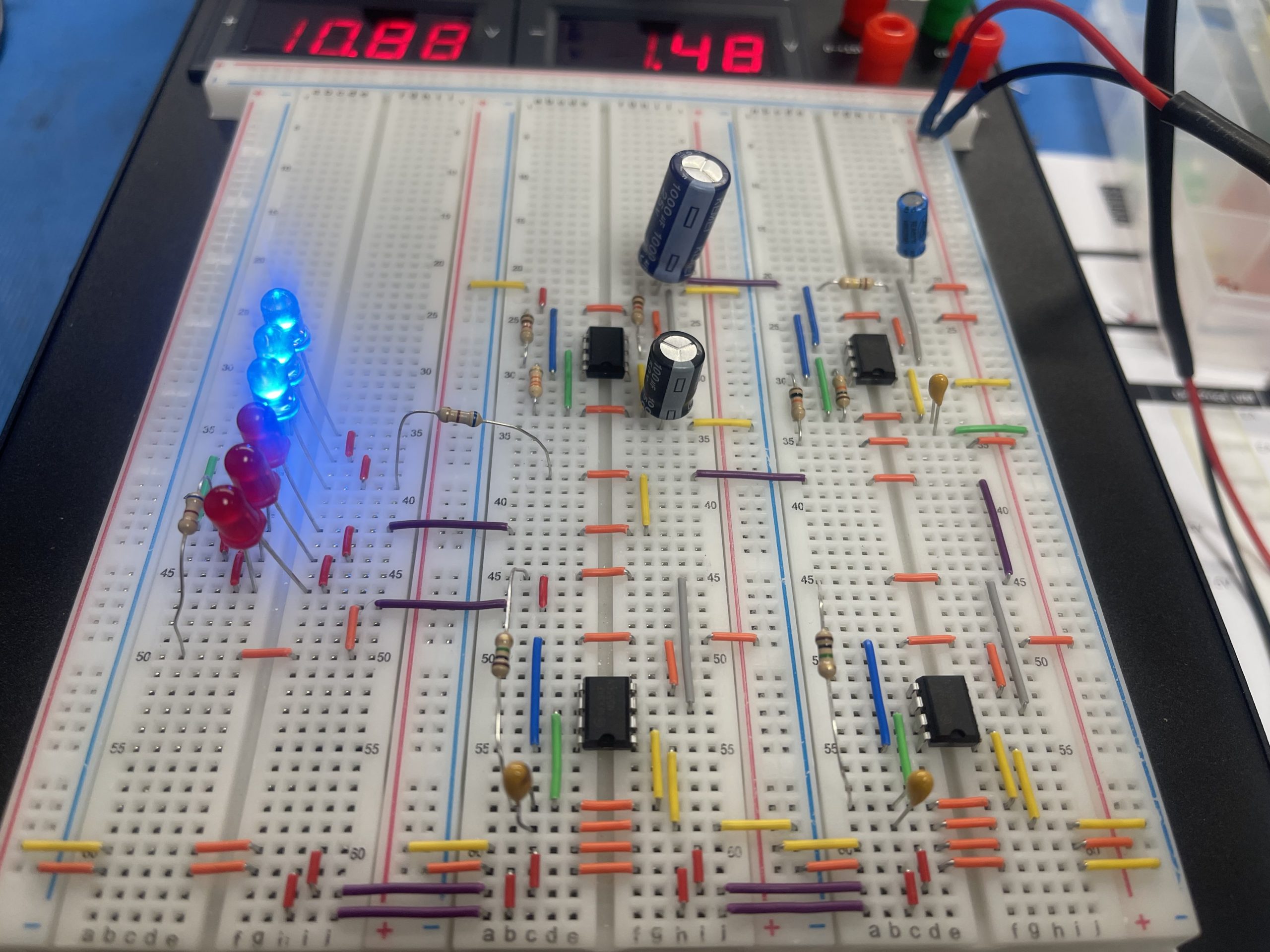
Similarly, the second group of LEDs (Blue LEDs) turns ON only if the output of the first 555 timers IC is OFF and the output of the second 555 timer IC is ON.
So when the output of the first 555 timers IC is ON, only the first group of LEDs have a chance of turning ON and they blink at the speed with which the second 555 timer IC toggles the output.
Similarly, when the first 555 timer IC turns OFF, only the second group of LEDs have a chance of turning ON and they blink at the speed with which the second 555 time IC toggles the output.
The Red LEDs turn ON when the first timer’s output is ON and the second timer’s output is OFF. The Blue LEDs turn ON when the first timer’s output is OFF and the second timer’s output is ON. This creates a flashing effect similar to police car lights.
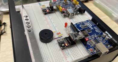
From Prototype to Final Product
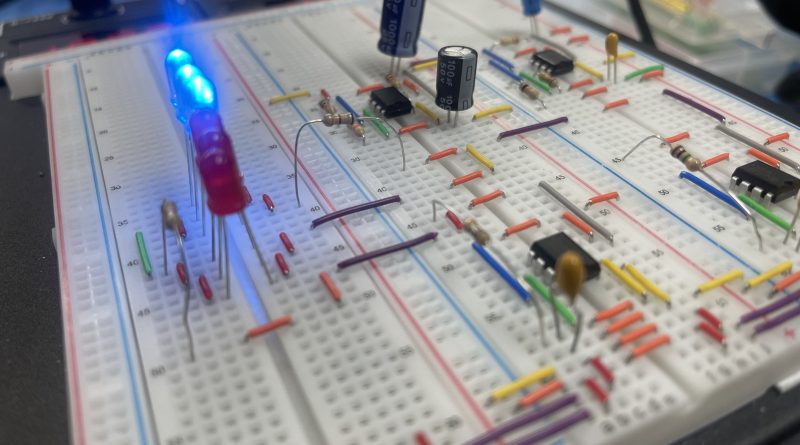
We started by building the Police LED Flashing Circuit and Police Siren Circuit on a Power Breadboard PBB-272B as prototypes. Then, we took the prototypes and turned them into a finished product by soldering the circuits onto a solderable board, adding a speaker and lights, and enclosing it in an aluminum enclosure. This finished product is the Emergency! Box, is a module system that can be expanded to cover a larger area.
What is an Emergency! Box?
An Emergency! Box is a module system containing equipment, supplies, and medications needed to provide an initial assessment and manage life-threatening conditions. In this case, our box provides a sound and light beacon during emergencies like storms or car accidents.
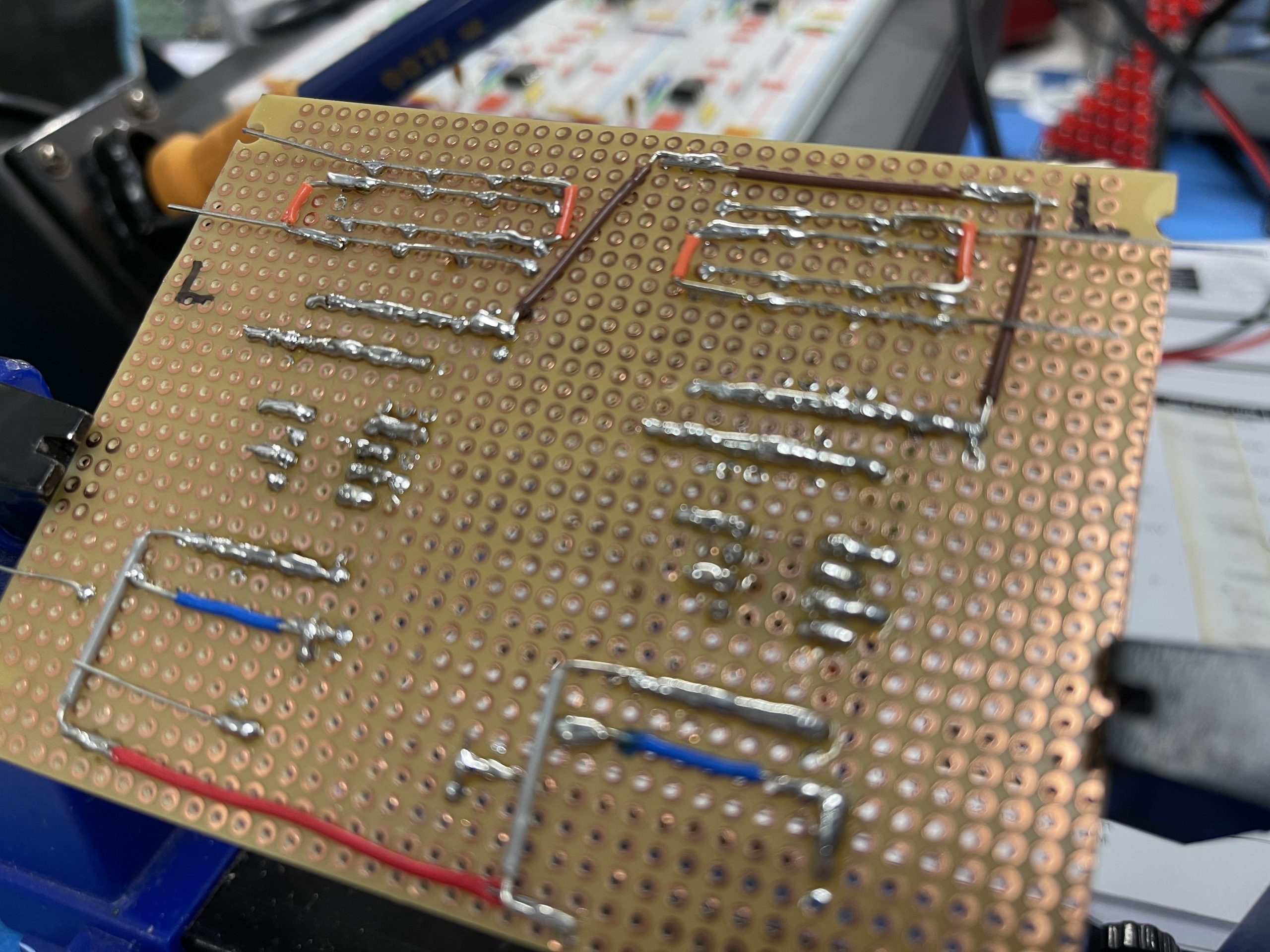
Build the Circuits onto a Solderable Board
First, lay down the components.
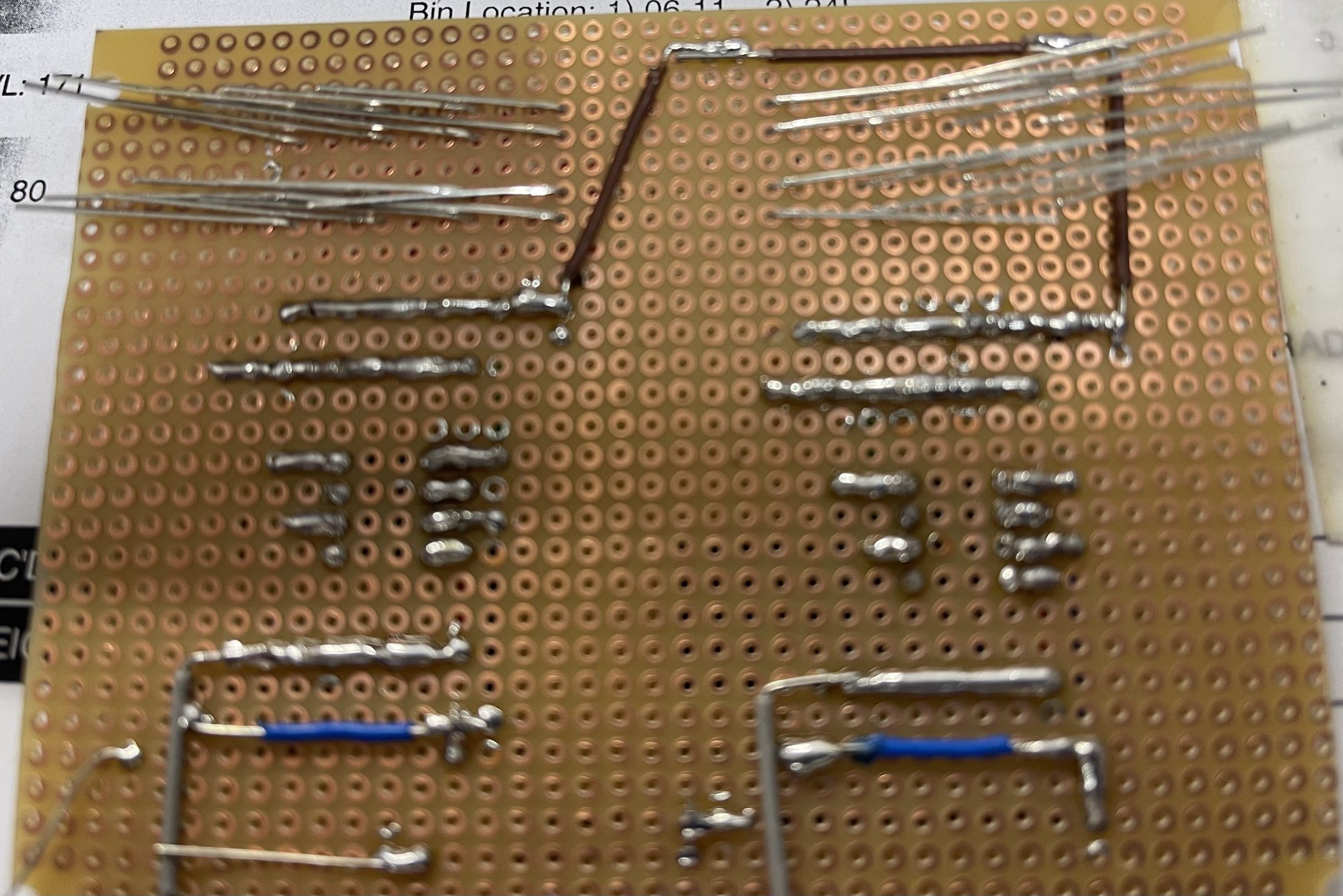
Then solder the path according to the schematic.
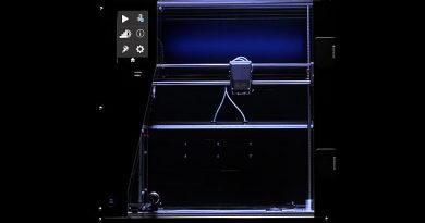
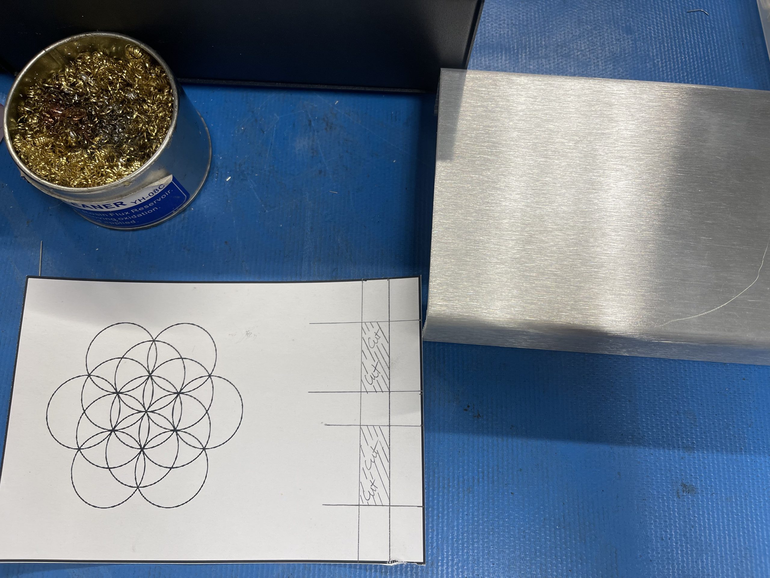
How to Cut the Pattern for Speaker and Light
First, print the pattern.
Then, snap your finger!
How to wire the Emergency! Box
First, look at the schematic.
Then solder accordingly.
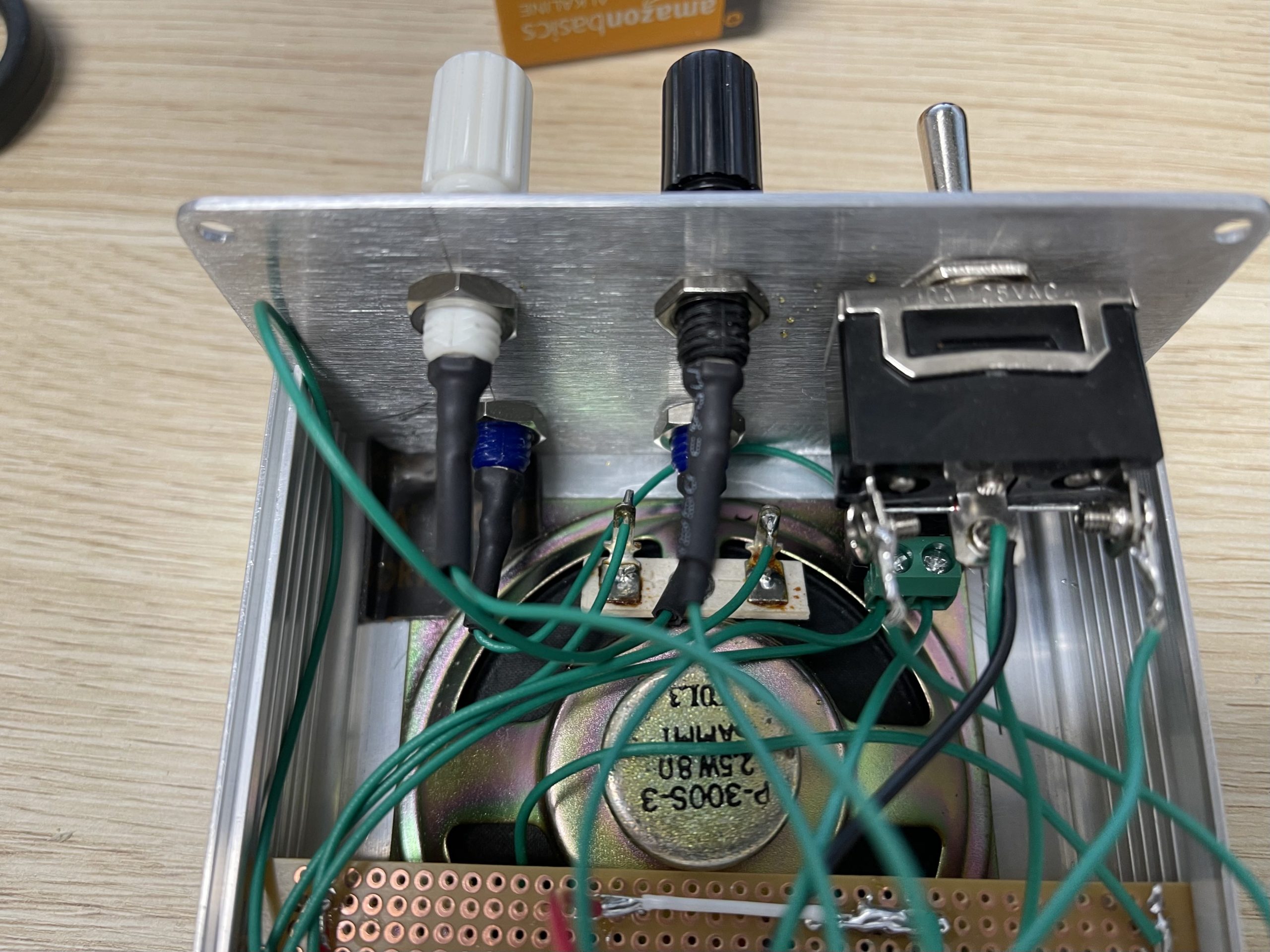
Finally, connect the battery before closing the unit up.
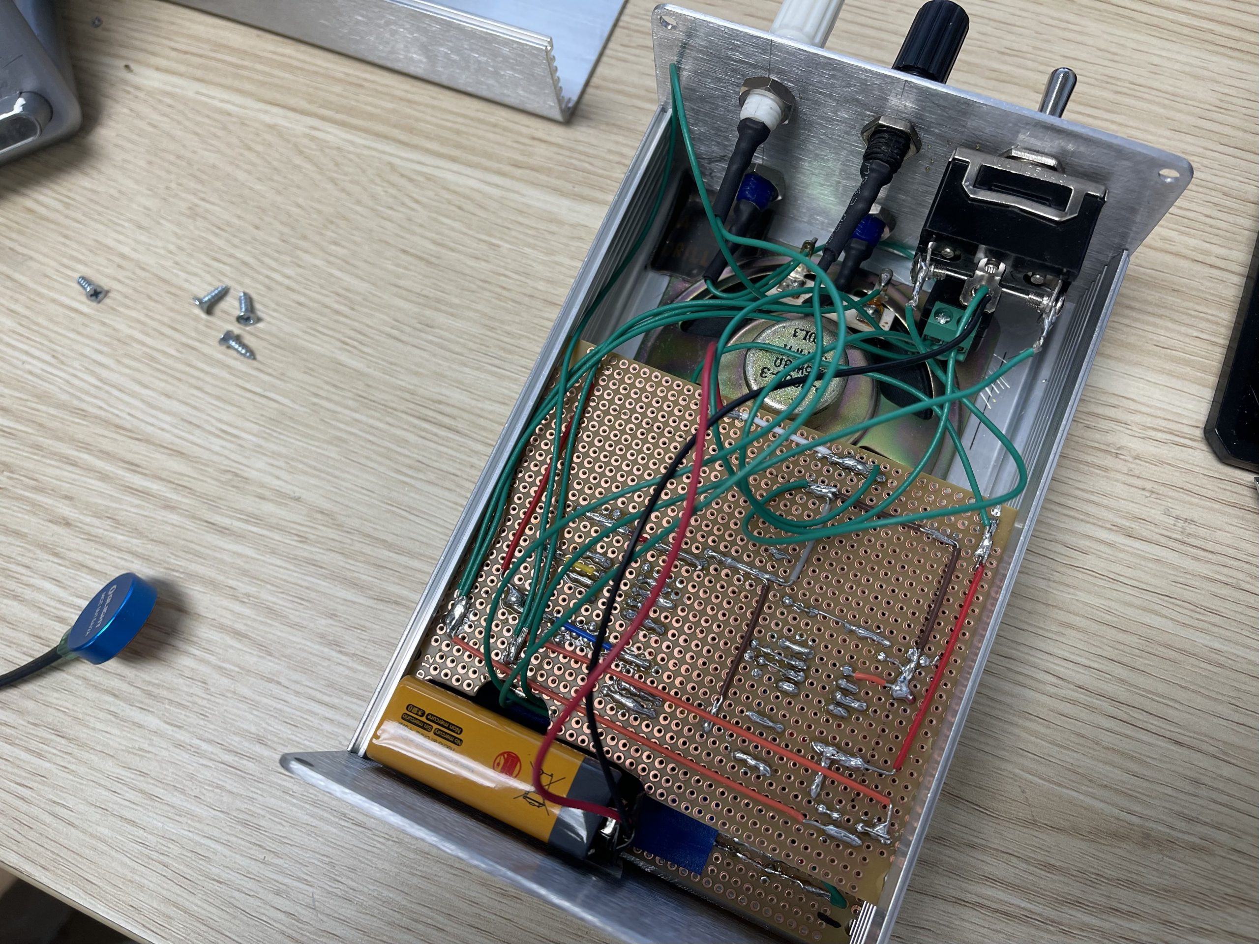
Reassemble the enclosure after testing.
Conclusion
In this tutorial, we successfully took a prototype to a final product using a Power Breadboard PBB-272B. The Emergency! Box is a module system that can be expanded to cover a larger area. By following these steps, you’ll be able to transform your prototype into a finished product. With the Power Breadboard PBB-272B, prototyping to finished product has never been easier.